Speed reducer lubricated through fuel injection pipe

A technology of fuel injection pipe and reducer, which is applied in the direction of gear lubrication/cooling, etc., can solve the problems of insufficient oil quantity at the contact point, failure of lubricating oil in time, cooling and cooling, etc., and achieve comprehensive lubrication effect.

Inactive Publication Date: 2015-02-11
JIANGSU TAILONG MACHINERY GRP CO CO LTD
View PDF6 Cites 2 Cited by
  • Summary
  • Abstract
  • Description
  • Claims
  • Application Information

AI Technical Summary

Problems solved by technology

The limitation of this lubrication method is that the lubricating oil will gradually decrease during the rotation of the gears, and the amount of oil at the contact point is not enough when meshing. At the same time, a large amount of heat is generated during meshing, and the lubricating oil cannot cool down in time.

Method used


Image

  • Speed reducer lubricated through fuel injection pipe
  • Speed reducer lubricated through fuel injection pipe

Examples


Embodiment Construction

[0010] Below in conjunction with accompanying drawing, the specific embodiment of the present invention is described in further detail:

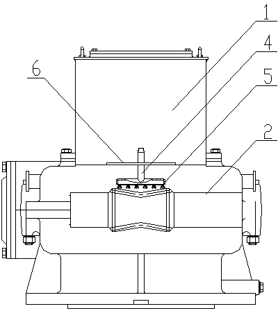
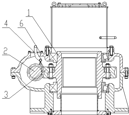
[0011] As shown in the figure, a reducer lubricated by an oil injection pipe includes a housing 1, a worm gear mechanism is arranged in the housing, and an oil injection pipe 4 is arranged above the meshing part of the worm wheel 3 and the worm 2, so that The fuel injection pipe 4 is a T-shaped fuel injection pipe, and the bottom of the horizontal section of the fuel injection pipe 4 is uniformly provided with a plurality of small holes 5, and the horizontal section of the fuel injection pipe is correspondingly arranged on the meshing section of the worm wheel 3 and the worm 2 Directly above, one end of the vertical section of the fuel injection pipe protrudes from the sight hole cover 6 of the casing 1 .


PUM


Abstract

The invention relates to a speed reducer lubricated through a fuel injection pipe. The speed reducer comprises a casing, wherein a worm and gear mechanism is arranged in the casing; the fuel injection pipe is arranged above a position where a worm gear is meshed with a worm; the fuel injection pipe is T-shaped; a plurality of small holes are formed in the cross section of the fuel injection pipe; the cross section of the fuel injection pipe is correspondingly arranged right above the meshing sections of the worm gear and the worm; one end of the vertical section of the fuel injection pipe extends out from a sight hole cover of the casing. The speed reducer lubricates gears through the T-shaped fuel injection pipe, the cross section of the T-shaped fuel injection pipe completely covers the meshing sections of the two gears, the fuel injection pipe always supplies lubricating oil to the meshing sections and cools the meshing sections during meshing operation of the gears, and the gears are more completely lubricated.

Description

technical field [0001] The invention relates to the field of reducers, in particular to a reducer lubricated by an oil injection pipe. Background technique [0002] In the prior art, the lubrication of the internal gear of the reducer mostly adopts the mode of an oil pool, the gear is half immersed in the oil pool, and the lubricating oil is attached during the rotation of the gear for lubrication. The limitation of this lubrication method is that the lubricating oil will gradually decrease during the rotation of the gears, and the amount of oil at the contact point is not enough during meshing. At the same time, a large amount of heat is generated during meshing, and the lubricating oil cannot cool it in time. Contents of the invention [0003] The object of the present invention is to provide a reducer lubricated by an oil injection pipe which can effectively lubricate and cool the gears. [0004] For achieving above object, the technical sch...

Claims


Application Information

Patent Timeline
Patent Type & Authority Applications(China)
IPC IPC(8): F16H57/04
CPCF16H57/04
Inventor 殷爱国叶青孔霞张介禄于琴
Owner JIANGSU TAILONG MACHINERY GRP CO CO LTD
Why Eureka
Try Eureka