
Pressure chamber lubrication method and device of die-casting machine

A lubricating device and die-casting machine technology, applied in the field of casting, can solve problems such as insufficient lubrication, and achieve the effects of comprehensive lubrication, improved production efficiency, and good flow

Inactive Publication Date: 2014-06-18
HUAZHONG UNIV OF SCI & TECH
View PDF5 Cites 0 Cited by
  • Summary
  • Abstract
  • Description
  • Claims
  • Application Information

AI Technical Summary

Problems solved by technology

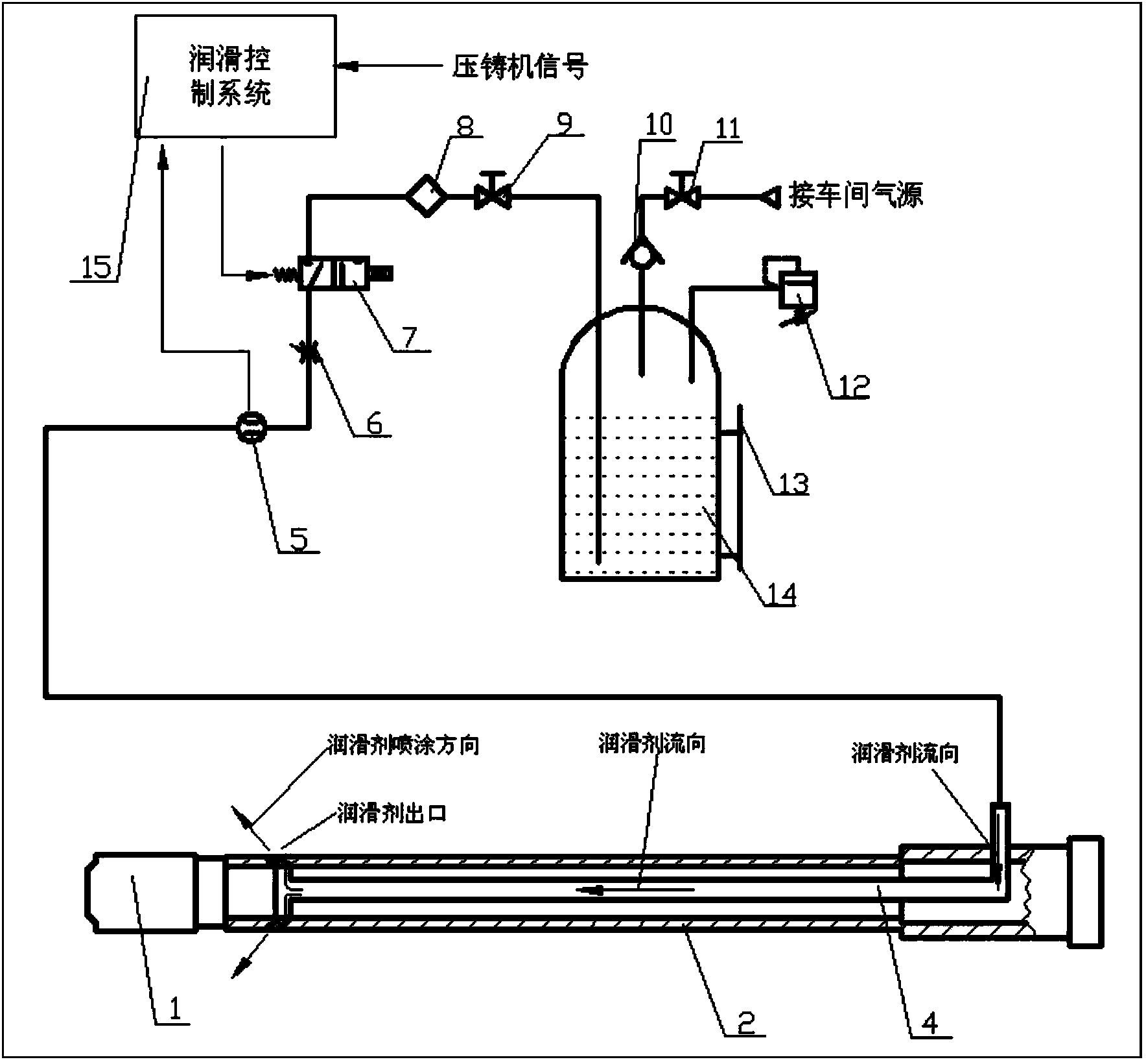
[0004] Aiming at the defects of the prior art, the object of the present invention is to provide a pressure chamber lubrication device for a die-casting machine, which aims to solve the problem of insufficient lubrication existing in the existing device

Method used


Image

  • Pressure chamber lubrication method and device of die-casting machine
  • Pressure chamber lubrication method and device of die-casting machine
  • Pressure chamber lubrication method and device of die-casting machine

Examples


Embodiment 1

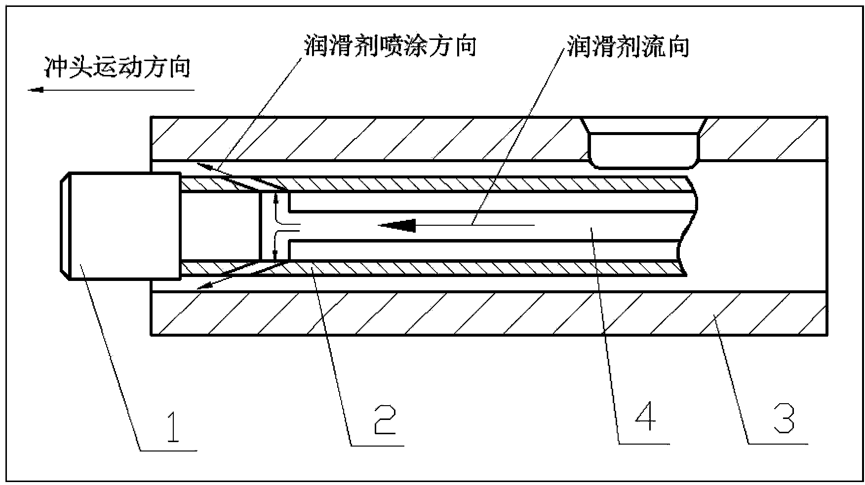
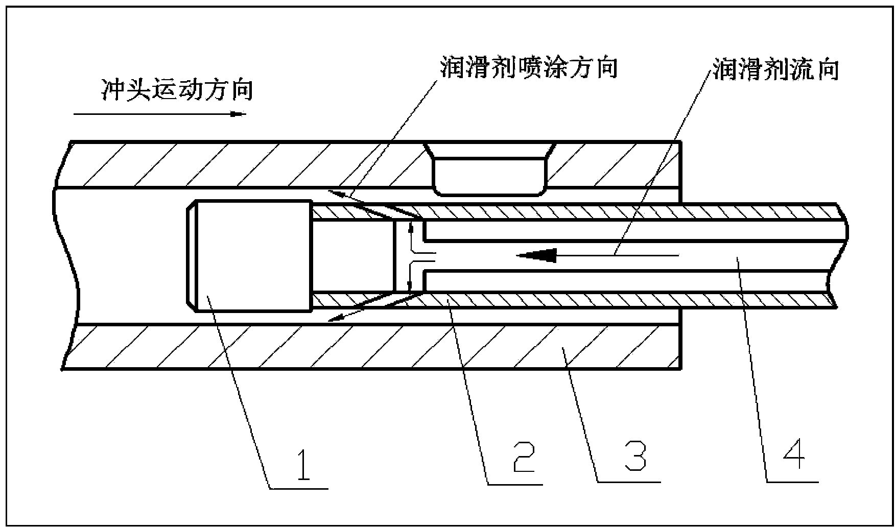
[0052] According to the lubricating method in the pressure chamber and related devices of the present invention, the ZL101 alloy is die-cast on a 2800KN horizontal cold chamber die-casting machine. The pressure inner diameter of the die-casting machine is 50 mm, the length of the punch is 80 mm, and the lubricant outlet is 6 oblique holes with a diameter of 3 mm. Before die-casting, install the lubricating device according to the instructions, and adjust the throttle valve to make the flow of lubricant meet the process requirements. The pouring temperature of die-casting is 670°C, the slow injection speed is 0.25m / s, the high speed is 3m / s, and the injection specific pressure is 70Mpa. Under the above process conditions, the pressure chamber and the punch are lubricated by the method of lubricating the pressure chamber, and the die-casting water-based paint is used as the lubricant. When the shoot rod is retracted, the lubricating device can accurately spray the lubricant on ...

Embodiment 2

[0055] Die-casting is carried out on a 16000KN horizontal cold-chamber die-casting machine using this pressure chamber lubrication method. The diameter of the pressure chamber is 110mm, and the lubricant outlet is 6 oblique holes with a diameter of 5mm. ZL104 alloy is used for die-casting. The pouring temperature is 670°C and slow injection. The speed is 0.25m / s, the high speed is 3m / s, and the injection specific pressure is 70Mpa. Adjust the throttle valve to make the lubricant flow appropriate. The lubricant sprayed on the surface of the pressure chamber can dry quickly to form a lubricating layer. After multiple die-casting cycles on the machine, the lubrication between the pressure chamber and the punch is good, and the punch has no abnormal wear. The lubricating layer is under the action of the molten metal. No smoke was produced. Therefore, the amount of gas generated by the lubricant is very small, and it does not pollute the molten metal and the environment on site. ...


PUM


Abstract

The invention discloses a pressure chamber lubrication method and a device of a die-casting machine. The pressure chamber lubrication method and the device of the die-casting machine comprise a punch, a plunger rod, a pressure chamber, a lubricant conveying pipeline, a flow meter, a throttle valve, a magnetic valve, a filter, a first manual stop valve, a one-way valve, a second manual stop valve, a safety valve, a liquid level meter, a liquid storage tank and a lubrication control system. The liquid storage tank is connected with the first manual stop valve and is used for storing lubricants, the first manual stop valve is used for stopping conveying of the lubricants in an emergency, the magnetic valve is connected with the filter and used for controlling on-off states of spraying of the lubricants, the magnetic valve, the throttle valve and the flow meter are sequentially connected, the throttle valve and the flow meter are respectively used for adjusting and displaying the flow of the lubricants, the lubricant conveying pipeline is arranged in the plunger rod and is connected with the flow meter, and an input end of the lubrication control system is connected with the die-casting machine and used for receiving plunger rod outgoing signals and plunger rod return signals of the die-casting machine. The pressure chamber lubrication method and the device of the die-casting machine can solve the problem of insufficient lubrication in the prior art.

Description

technical field [0001] The invention belongs to the technical field of casting, and more specifically relates to a method and device for lubricating a pressure chamber of a die-casting machine. Background technique [0002] During die casting production, the liquid metal flows into the mold cavity at high speed under the push of the injection punch, and then fills the cavity under high pressure and finally cools and forms. As the pressure chamber and the punch that are in direct contact with the liquid metal work at high temperature for a long time, the punch moves at a high speed relative to the pressure chamber during injection, and bears a large injection force. Therefore, in order to ensure that the punch completes the normal injection process and prolong the service life of the punch, lubrication must be carried out between the punch and the pressure chamber. [0003] At present, there are two main lubrication methods between the punch and the pressure chamber, one is ...

Claims


Application Information

Patent Timeline
Patent Type & Authority Patents(China)
IPC IPC(8): B22D17/20
Inventor 万里邹广吴树森
Owner HUAZHONG UNIV OF SCI & TECH
Learn More