Electromagnetic hydraulic valve

A hydraulic valve and electromagnetic technology, applied in the field of electromagnetic hydraulic valve, can solve the problems of increased pressure loss, tight construction cost, high pressure loss of hydraulic medium, etc., and achieve the effects of simple annular sleeve, low production cost, and simple installation

Active Publication Date: 2008-07-30
SCHAEFFLER TECH AG & CO KG
View PDF1 Cites 15 Cited by
  • Summary
  • Abstract
  • Description
  • Claims
  • Application Information

AI Technical Summary

Problems solved by technology

However, the installation of a second filter element is associated with correspondingly high and cost-intensive construction costs
[0006] In addition, fine or finest filters can be installed in order to suppress very small particles, but at the inlet

Method used


Image

  • Electromagnetic hydraulic valve
  • Electromagnetic hydraulic valve

Examples


Embodiment Construction

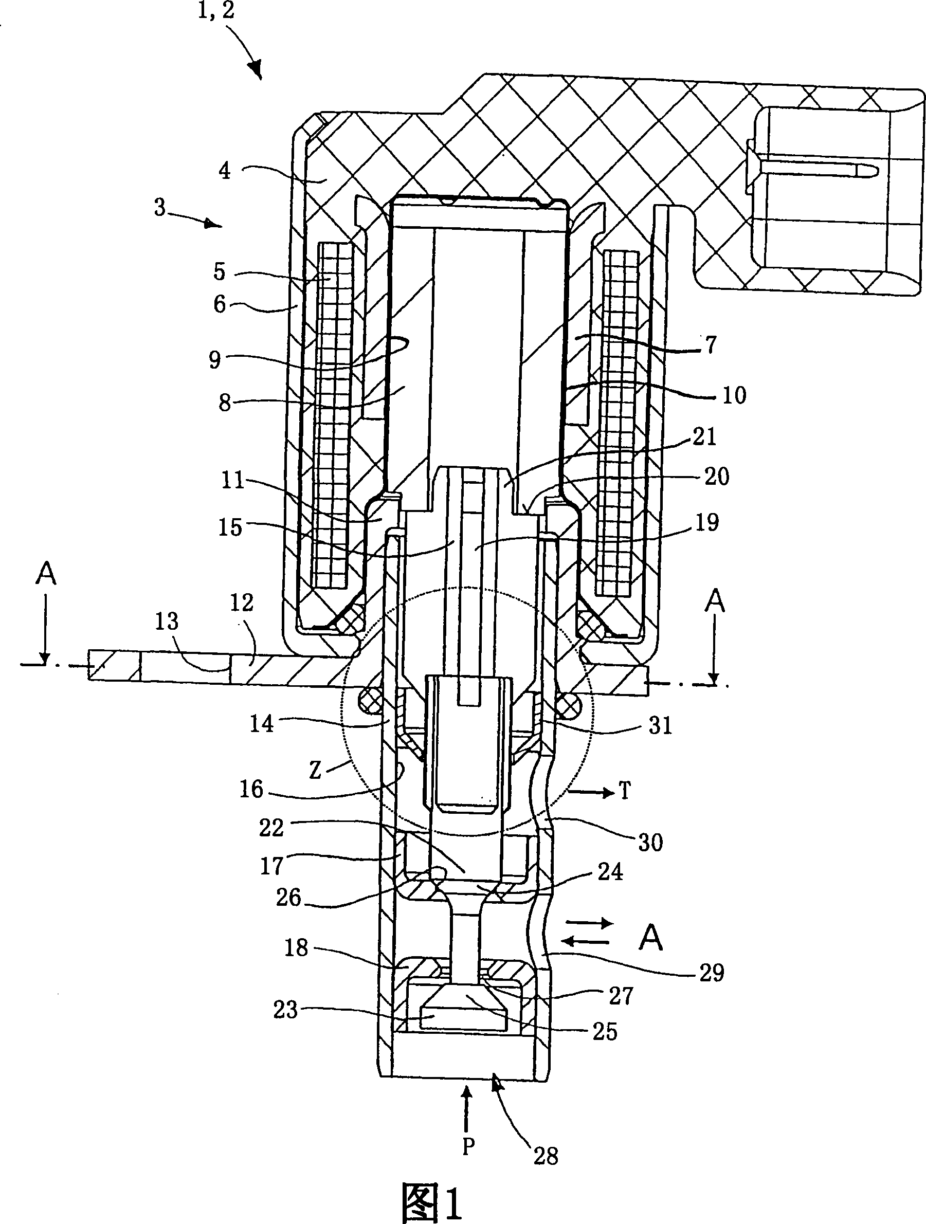
[0020] FIG. 1 shows an electromagnetic hydraulic valve source 1 which is designed as a 3 / 2-way valve 2 and which can be used to control a variable valve drive of an internal combustion engine (not shown). The hydraulic valve 1 consists of an electromagnet 3 with a coil winding 5 cast from plastic in a coil body 4 in a magnet housing 6 . A sleeve 7 , which is likewise injected into the coil body 4 , serves as the upper magnetic pole of the armature 8 , said sleeve surrounding a non-magnetic metal sleeve 10 serving as the armature guide 9 , in which the armature 8 is guided in a longitudinally displaceable manner. The lower magnetic pole is formed by an annular band 11 , which is turned toward the internal combustion engine in a suitable position in a flange region 12 with screw holes 13 for fastening the hydraulic valve 1 .

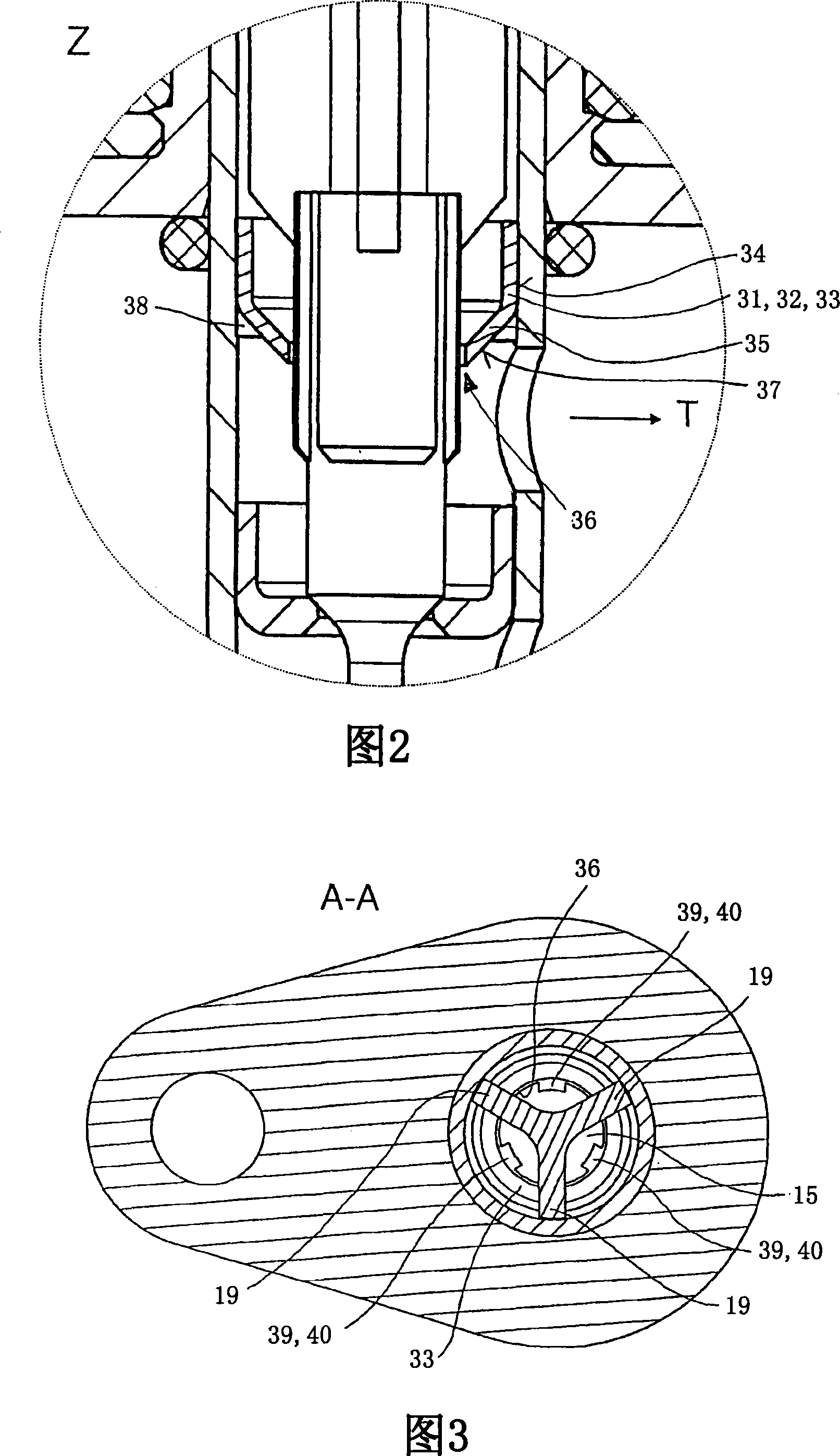
[0021] In the annulus 11 of the lower pole there is also accommodated the upper part of the valve box 14 facing the electromagnet 3 . The valve housing 1...


PUM


Abstract

The invention relates to an electromagnetic hydraulic valve (1) comprising an armature (8) guided in longitudinal movement in an armature guide (9) actuating valve tappets (15) distributed in a valve box (14) ). Said valve lifters control the connection between interface holes (28, 29, 30) for hydraulic medium formed in the valve box (14), wherein the valve lifters (15) are connected to one or more sealing bodies (22 , 23) form an effective connection, and the sealing body corresponds to one or more sealing sleeves (17, 18) supported on the valve box (14). The hydraulic valve (1) has a mechanism for depositing dirt particles, which consists of a partition (31) arranged between the armature guide (9) and the connecting holes (28, 29, 30). Said partition forms a hydraulic seal with the inner surface (16) of the valve box (14), wherein the valve box (14) consists of a magnetizable material for the purpose of depositing ferromagnetic dirt particles.

Description

technical field [0001] The invention relates to an electromagnetic hydraulic valve comprising an armature guided in longitudinal movement along an armature guide, said armature actuating valve tappets distributed in a valve box. The valve lifter controls the connection between connection holes formed in the valve box for the hydraulic medium, wherein the valve lifter establishes an operative connection with one or more sealing bodies which communicate with one or more Corresponding to a sealing sleeve supported on the valve box, where the hydraulic valve has a mechanism for depositing dirt particles. Background technique [0002] Hydraulic valves are known in the prior art which, in order to ensure the continuous reliability of the hydraulic valve, have their own or downstream distributed component mechanisms for depositing dirt particles from the hydraulic medium. Such dirt particles are present as suspended particles in the hydraulic medium in hydraulic valves and are ori...

Claims


Application Information

Patent Timeline
IPC IPC(8): F16K31/06F16K11/048
CPCF01L2001/3443F15B13/044F16K11/048F16K31/0634Y10T137/86622Y10T137/794Y10T137/8013F16K31/06
Inventor 克里斯托弗·罗斯赫贝特·施特克尔
Owner SCHAEFFLER TECH AG & CO KG
Why Eureka
Try Eureka