Gas spring

A gas spring and elastic technology, which is applied in the field of suspension system of military motor vehicles, can solve the problems of inability to adjust in real time, complex electronic control system, high production cost and maintenance cost, and achieve the effect of good lubrication and increased stiffness

Inactive Publication Date: 2007-06-06
杨德君
View PDF0 Cites 15 Cited by
  • Summary
  • Abstract
  • Description
  • Claims
  • Application Information

AI Technical Summary

Problems solved by technology

In order to adapt the suspension to various road surfaces, the adjustment of the suspension stiffness and damping force can only be adapted to the road section, and cannot be adjusted in real time in response to each road obstacle point
The electronic control system of active suspension equipped with adjustable stiffness rubber air spring and damping adjustable shock absorber is also very complicated, so the production cost and maintenance cost of this suspension device are very high, which is not conducive to the popularization and use of air suspension

Method used


Image

  • Gas spring
  • Gas spring
  • Gas spring

Examples


Embodiment 1

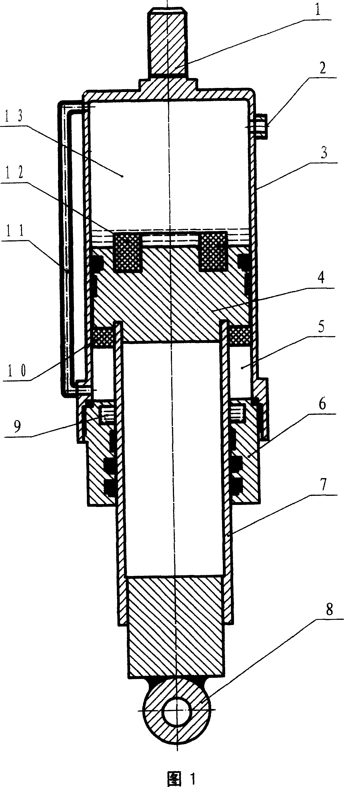
[0033]The gas spring proposed by the present invention is mainly composed of a cylinder body 3 connected with an end cover 6, a piston body 4 fitted in the cylinder body 3 and connected with a piston rod 7, and an upper connecting piece 1 is arranged on the top of the cylinder body 3. , there is a lower connector 8 at the bottom of the piston rod 7, a lubricating oil chamber 9 is arranged on the end cover 6 of the cylinder body 3 and the piston rod 7 of the piston body 4, and an anti-collision chamber is embedded on the piston body 4. The rubber pads 10, 12, the piston body 4 fitted in the cylinder body 3 separate the cylinder body 3 from the main elastic air cavity 13 and the secondary elastic air cavity 5, and damping is arranged between the main elastic air cavity 13 and the secondary elastic air cavity 5 The air duct 11 constitutes a closed air compression system. As a gas spring for suspension, it works like this: the upper connecting piece 1 and the lower connecting piec...

Embodiment 2

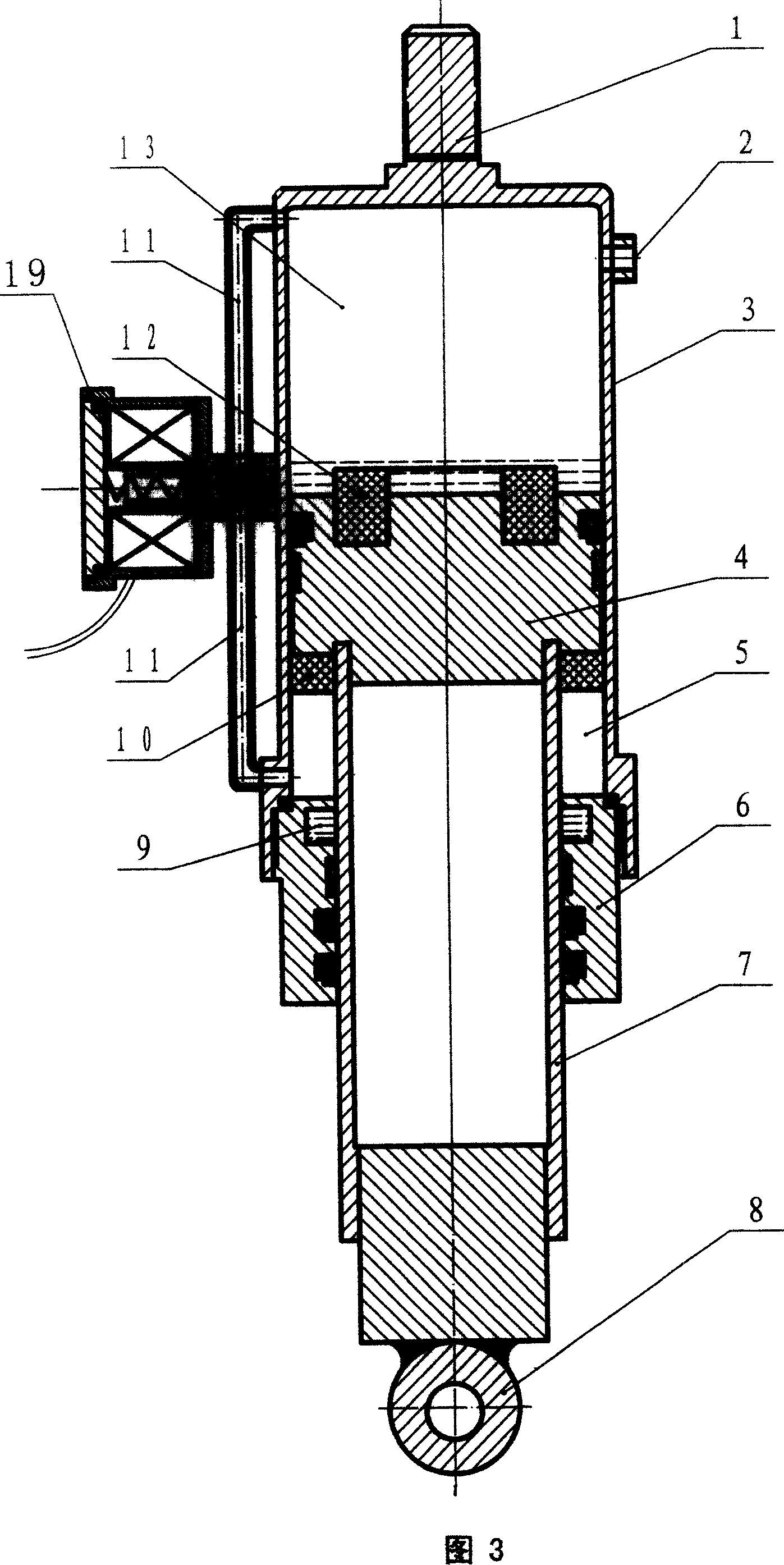
[0035] On the basis of the implementation described in Example 1, the damping air passage 11 can be arranged in the cylinder wall of the cylinder block 3, that is to say, when casting and producing the parts of the cylinder block 3, it can be processed and manufactured in a pre-embedded manner. The damping air passage 11 is provided, so that gas spring products can be produced in batches more conveniently.

Embodiment 3

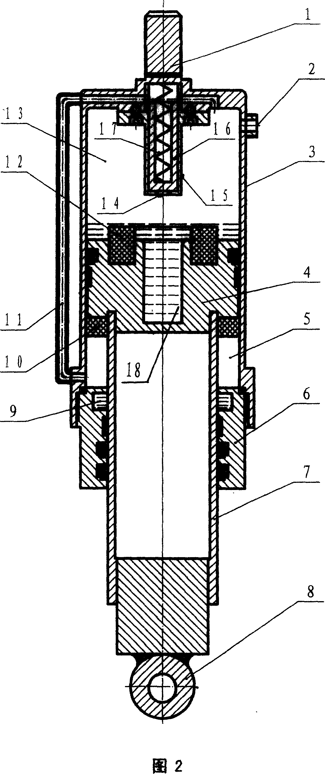
[0037] On the basis of the implementation described in Example 1, a stroke valve 15 that can open or close the damping air passage 11 is equipped in the cylinder body 3, and a valve that is compatible with the stroke valve 15 is provided at the corresponding position of the piston body 4. The oil cylinder 18 is equipped with a spring 17 on the spool 16 of the stroke valve 15. When the piston body 4 moves up and down in the cylinder body 3 and the stroke valve 15 enters or exits the oil cylinder, the oil in the gap between the oil cylinder 18 and the stroke valve 15 Under the damping force of the medium, the oil medium will force the valve core 16 to move up and down through the hole 14 of the travel valve 15, thereby controlling the opening or closing of the damping air passage 11. The function of the spring 17 is to change the gas spring from compression to elongation. The instantaneous acceleration of the spool 16 moves downward to quickly open the damping air passage 11. Whe...


PUM


Abstract

There is disclosed a gas springs, in which a closed air compression system made up of a damping air passage is disposed between main and secondary elastic air cavities formed by separating the cylinder body via the piston. By using the damping force action of the damping air passage on the medium, there is unequal gas pressure in the main and secondary air cavities. When the piston up and down moves under the action of the external force, i.e., the gas spring is expressed externally as compression or extension, it can automatically regulate its rigid change to balance the action adapted to external force.

Description

Technical field: [0001] The invention relates to an elastic buffer device composed of an air compression system, which is a gas spring, which is suitable for automobiles, trains and other motor vehicles, aircraft landing gear and other buffer devices, especially for the suspension of military motor vehicles such as tanks and armored vehicles system. Background technique: [0002] The gas spring has a conic elastic change characteristic close to the ideal spring, and is widely used in the suspension system of luxury passenger cars and some high-end cars. Although the rubber air spring commonly used in active suspension devices has a simple structure, the compression stiffness and elongation stiffness change according to the same curve. The shock absorber provides a resistance against the elastic force to prevent the rapid extension of the spring from oscillating. In order to make the suspension adapt to various road surfaces, the adjustment of the suspension stiffness and d...

Claims


Application Information

Patent Timeline
Patent Type & Authority Applications(China)
IPC IPC(8): F16F9/34F16F9/32F16F9/38F16F9/02
Inventor 杨德君王红英
Owner 杨德君
Why Eureka
Try Eureka