Fuzzy positioning based elastic shaft hole automated assembly device and assembly method thereof

A technology of fuzzy positioning and assembling device, applied in metal processing, metal processing equipment, manufacturing tools, etc., can solve the problems of limited precision, low practical value and large matching gap of robot vision technology, and achieve simple structure, low cost, The effect of reducing manufacturing costs

Active Publication Date: 2014-12-17
KUNSHAN TUNGRAY IND AUTOMATION
View PDF8 Cites 6 Cited by
  • Summary
  • Abstract
  • Description
  • Claims
  • Application Information

AI Technical Summary

Problems solved by technology

Problems and deficiencies in this method: 1. The precision of robot vision technology is limited. At present, the gap between the shaft holes reaches the um level. In addition, the assembly of shaft holes is not only complicated in size deviation, shape and position tolerance, etc. Robot vision There are technical difficulties in solving this problem; 2. The cost is high. The accuracy of robot vision technology depends on the high-speed and high-resolution image acquisition device. This device basically relies on imports and is expensive. In addition, it is also expensive when used with corresponding robots.
With the development of robot vision technology, the application fields of the above-mentioned technologies will be expanded, but for now, due to their own problems of precision and price, they are only suitable for applications with low precision and large fit gaps. Little practical value

Method used


Image

  • Fuzzy positioning based elastic shaft hole automated assembly device and assembly method thereof
  • Fuzzy positioning based elastic shaft hole automated assembly device and assembly method thereof
  • Fuzzy positioning based elastic shaft hole automated assembly device and assembly method thereof

Examples


Embodiment Construction

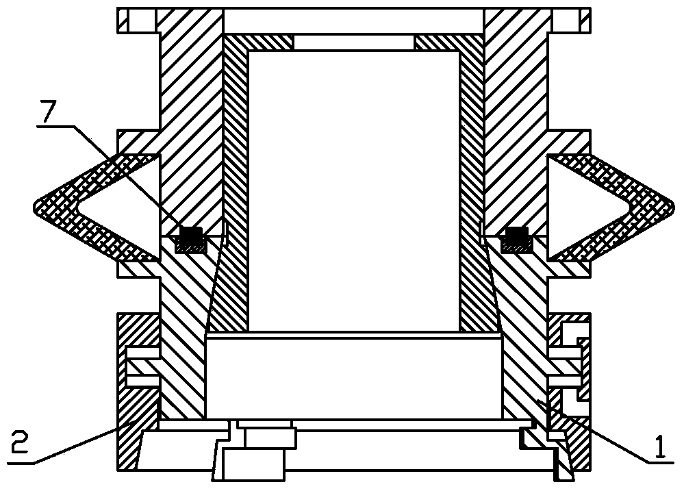
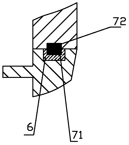
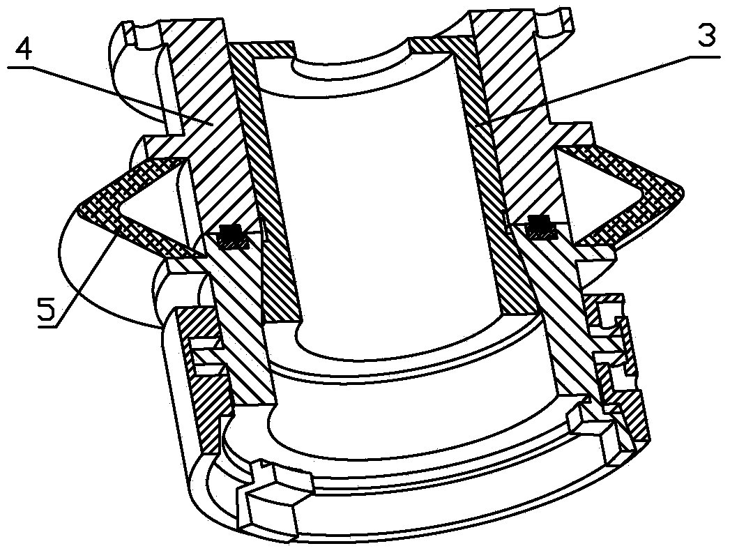
[0031] The accompanying drawings disclose, without limitation, the structural schematic diagrams of the preferred embodiments involved in the present invention; the technical solution of the present invention will be described in detail below in conjunction with the accompanying drawings.

[0032] Such as figure 1 , 2 As shown, the fuzzy positioning-based elastic automatic shaft hole assembly device of the present invention is a vertical structure as a whole, including a mandrel, a connecting seat, a sleeve, a bushing, an elastic connecting part, an insulating ring and a conductive ring, wherein, The mandrel is a tapered shaft, the sleeve is a tapered sleeve, the sleeve is a tapered sleeve, the elastic connecting part is a ring-shaped part made of elastic material (such as rubber, etc.), and the conductive ring includes two , are respectively the conductive ring a and the conductive ring b used together; the specific structure of each component is as follows:

[0033] The ta...


PUM


Abstract

The invention discloses a fuzzy positioning based elastic shaft hole automated assembly device and an assembly method thereof. The fuzzy positioning based elastic shaft hole automated assembly device comprises a mandrel, a connecting seat, a sleeve and a shaft sleeve, wherein the inner walls of the connecting seat and the shaft sleeve are respectively and slidably connected with the outer wall of the mandrel through a first motion pair and a cone matching connecting pair, and the outer wall of the connecting seat is elastically connected with the outer wall of the shaft sleeve; a conductive ring a is embedded in the end surface, adjacent to the connecting seat, of the shaft sleeve, and more than three clamping jaws are circumferentially arranged on the end surface, back to the connecting seat, of the shaft sleeve; a conductive ring b corresponding to the conductive ring a is embedded in the end surface, adjacent to the shaft sleeve, of the connecting seat, and the inner wall of the sleeve is slidably connected with the shaft sleeve through a motion pair, and is connected with the clamping jaws through a cone matching movable connecting pair; a driving cylinder is formed between the inner wall of the sleeve and the outer wall of the shaft sleeve. Therefore, the positioning precision can be far less than the assembly clearance of a shaft hole as long as the position is roughly correct, and the positioning precision reaches 0.1mm order of magnitudes.

Description

technical field [0001] The invention relates to an automatic assembly device for elastic shaft holes based on fuzzy positioning, which belongs to the field of automatic assembly of shaft holes in mechanical engineering. Background technique [0002] With the continuous improvement of the automation level of the equipment manufacturing industry, the automatic assembly of shaft holes has gradually attracted people's attention. In actual production, efficient and high-precision automatic assembly of shaft holes has become an urgent technical problem to be solved. In the process of automatic assembly of shaft holes, the shaft (workpiece) is usually moved to the corresponding position by clamping the shaft (workpiece) by an external drive mechanism such as a joint robot and a linear shaft motion mechanism for precise positioning, and then the shaft is inserted into the hole through the movement of the drive mechanism along the axis direction. , to complete the assembly operation....

Claims


Application Information

Patent Timeline
Patent Type & Authority Applications(China)
IPC IPC(8): B23P19/027
CPCB23P19/027
Inventor 徐丰羽王志惠
Owner KUNSHAN TUNGRAY IND AUTOMATION
Why Eureka
Try Eureka