Cloth cutter applied to spinning mill

A cutting machine and textile mill technology, applied in the cutting of textile materials, textiles and papermaking, etc., can solve the problems of inconvenient disassembly and assembly, blade damage, etc., and achieve the effects of convenient disassembly, time saving and convenient operation.

Inactive Publication Date: 2018-05-04
刘丽影
View PDF1 Cites 7 Cited by
  • Summary
  • Abstract
  • Description
  • Claims
  • Application Information

AI Technical Summary

Problems solved by technology

The present invention aims to provide a cloth cutting machine, which can prevent the cloth from slipping during the cutting process and increase the qualified rate of the product. This cloth cutting machine does not set a buffer module when cutting the cloth, and the blade is easy to Rigid collision and damage, and, in the prior art, the blades are all screwed and installed on the cloth cutting machine, and it is very inconvenient to disassemble when changing the blades, so the present invention proposes an improved method for the above problems

Method used


Image

  • Cloth cutter applied to spinning mill
  • Cloth cutter applied to spinning mill
  • Cloth cutter applied to spinning mill

Examples


Embodiment Construction

[0022] The following will clearly and completely describe the technical solutions in the embodiments of the present invention with reference to the accompanying drawings in the embodiments of the present invention. Obviously, the described embodiments are only some, not all, embodiments of the present invention.

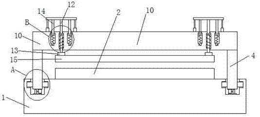
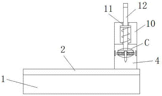
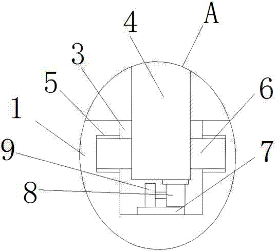
[0023] refer to Figure 1-5 , a cloth cutting machine used in textile mills, comprising a base 1, an operating platform 2 is fixedly installed on the top of the base 1, and two sides of the operating platform 2 are symmetrically provided with a chute 3 on the top of the base 1, the chute The support bar 4 is slidably installed in the chute 3, and the sliding module is arranged in the chute 3. The top of the two support bars 4 is welded with the same beam 10, and the top of the beam 10 is symmetrically opened with two first through holes 11. A first slide bar 12 is slidably installed in the hole 11, and both ends of the first slide bar 12 extend to the outside of the ...


PUM


Abstract

The invention discloses a cloth cutter applied to a spinning mill. The cloth cutter comprises a base. An operation platform is fixedly installed on the top of the base. Sliding grooves formed in the top of the base are symmetrically formed in the two sides of the operation platform. Supporting rods are installed inside the sliding grooves in a sliding mode. Sliding modules are arranged inside thesliding grooves. A beam is welded to the tops of the two supporting rods. Two first through holes are symmetrically formed in the top of the beam, first sliding rods are installed inside the first through holes in a sliding mode, the two ends of the first sliding rods extend out of the first through holes, buffer modules are symmetrically arranged on the two sides of the first sliding rods, installing blocks are welded to the bottoms of the sliding rods, installing grooves are formed in the bottoms of the installing blocks, and blades are installed inside the installing grooves. The cloth cutter is simple in structure and convenient to operate, rigid collision between the blades and the operation platform is effectively avoided, the blades can be quite convenient to disassemble, the time is shortened, and the disassembling efficiency is improved.

Description

technical field [0001] The invention relates to the technical field of cutting machines, in particular to a cloth cutting machine used in textile mills. Background technique [0002] Cloth cutting machine, as the name suggests, refers to a machine that cuts cloth into semi-finished cloth in blocks. This machine is widely used in the textile industry. [0003] The cloth cutting machine patent No. 201611172740.9 discloses a cloth cutting machine in a textile factory, which includes a rotating shaft. The end of the rotating shaft is provided with a driving motor to control its rotation. The rotating shaft is linked to the other end of the driving motor. There is a cloth cutting wheel, the trimming wheel is composed of a blade and a first guide wheel that fits with the blade, the worktable is provided with a cutter groove under the blade, and a second guide wheel is arranged on the other side of the blade in the cutter groove, A connecting rod parallel to the rotating shaft is ...

Claims


Application Information

Patent Timeline
Patent Type & Authority Applications(China)
IPC IPC(8): D06H7/00
CPCD06H7/00
Inventor 刘丽影
Owner 刘丽影
Why Eureka
Try Eureka