

Transmission of working vehicle
a technology for working vehicles and transmissions, applied in the direction of machines/engines, drip or splash lubrication, gearing, etc., can solve the problems of affecting the the difficulty of further miniaturization of the transmission, so as to reduce the manufacturing cost of the transmission, compactly and simply form, and save the effect of spa
- Summary
- Abstract
- Description
- Claims
- Application Information
AI Technical Summary
Benefits of technology
Problems solved by technology
Method used
Image

Examples
Embodiment Construction
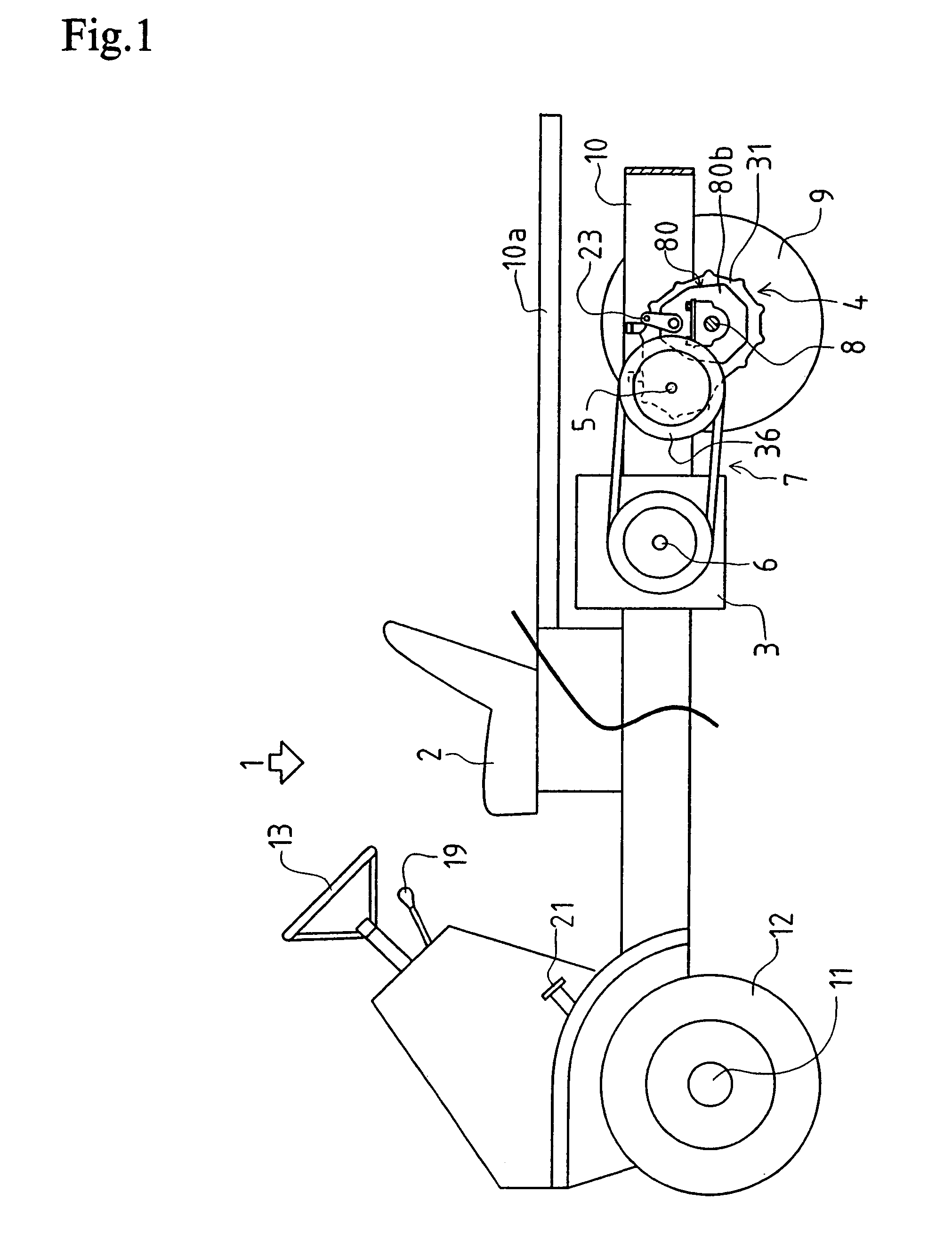
[0039]A truck 1 as an embodiment of the present invention is shown in FIG. 1. A bodywork frame 10 is disposed in the longitudinal direction of the vehicle. An engine 3 is mounted on the bodywork frame 10 at the rear of an operator's seat 2. The engine 3 is disposed such that its crankshaft (as an output shaft of the engine) 6 is horizontally oriented perpendicular to the longitudinal direction of the vehicle.
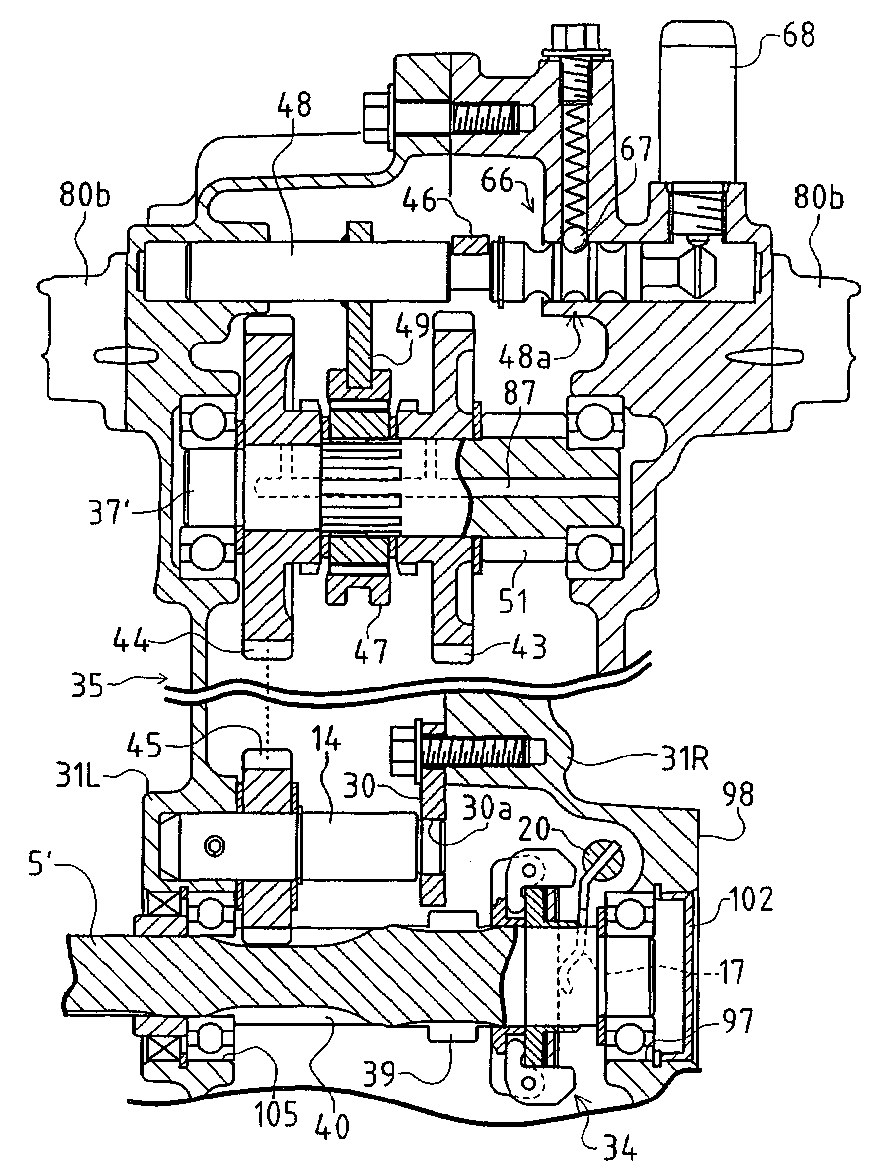
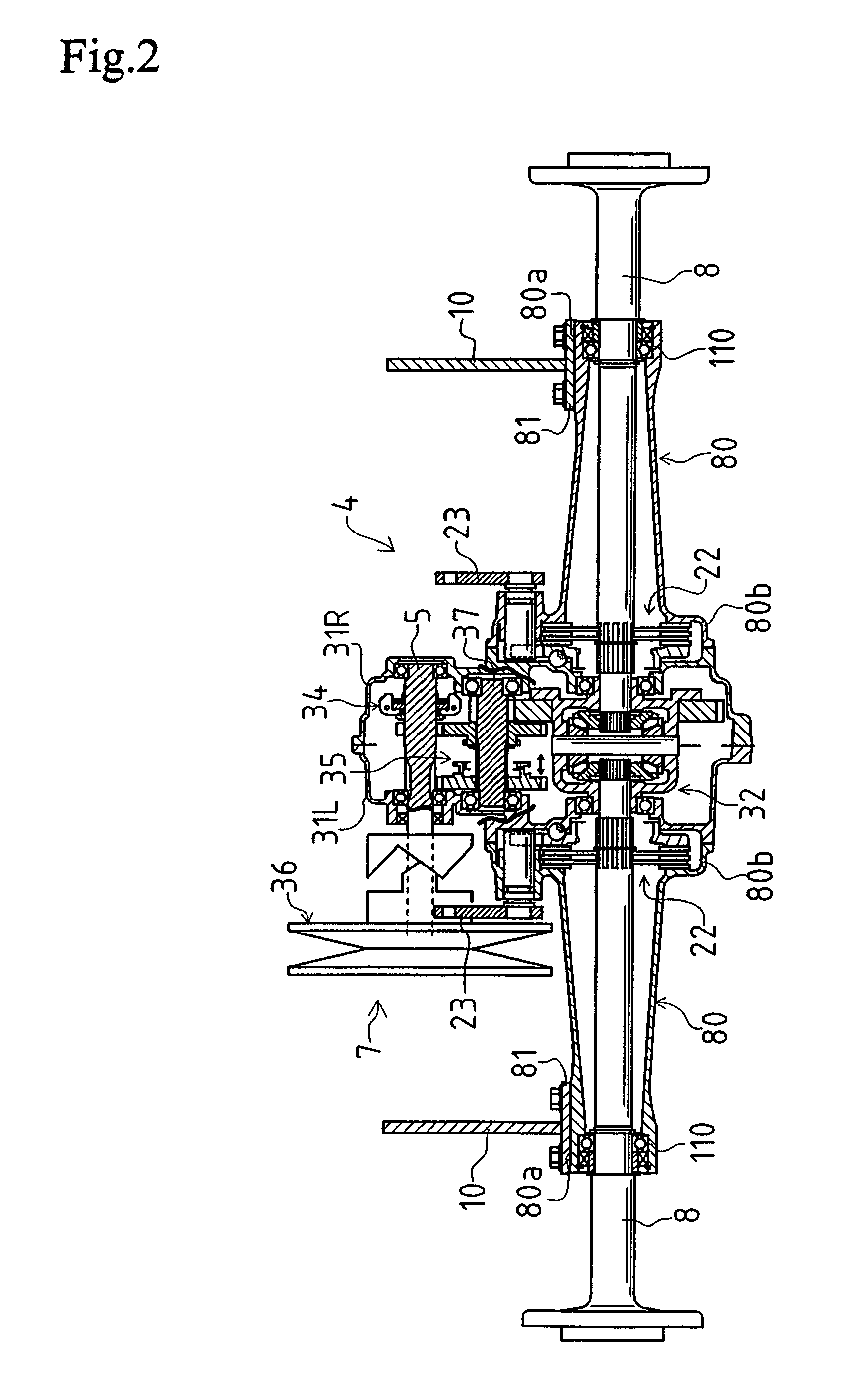
[0040]At the rear of the engine 3, a transmission 4 of the present invention is supported by the bodywork frame 10 through a pair of axle housings 80 (described below). A pair of left and right slender flat boards are disposed in a longitudinal direction of the vehicle and parallel to each other, and the rear end portion of the flat boards are connected with each other, thereby forming the bodywork frame 10 having a U-shape in a plan view. As shown in FIG. 2, axle housings 80 are fixed onto the bodywork frame 10 such that a housing 31 of the transmission 4 is located between the...
PUM
 Abstract
Description
Claims
Application Information