Novel wall air conditioning terminal

A technology for air-conditioning terminals and walls, applied in the field of decoration and decoration materials, to achieve the effect of simple structure, convenient paving and reasonable design

Inactive Publication Date: 2015-02-11
李渊
View PDF0 Cites 3 Cited by
  • Summary
  • Abstract
  • Description
  • Claims
  • Application Information

AI Technical Summary

Problems solved by technology

This new type of wall air conditioner terminal is usually used in combination with various heat pumps and their fresh air systems

Method used


Image

  • Novel wall air conditioning terminal
  • Novel wall air conditioning terminal
  • Novel wall air conditioning terminal

Examples


Embodiment 1

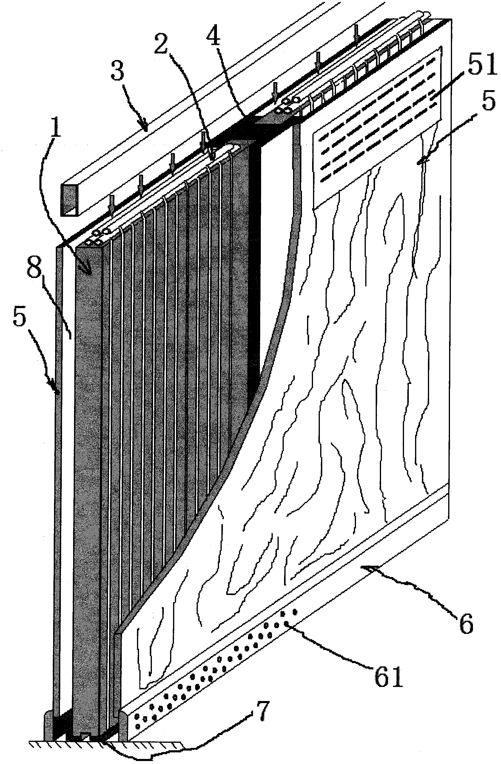
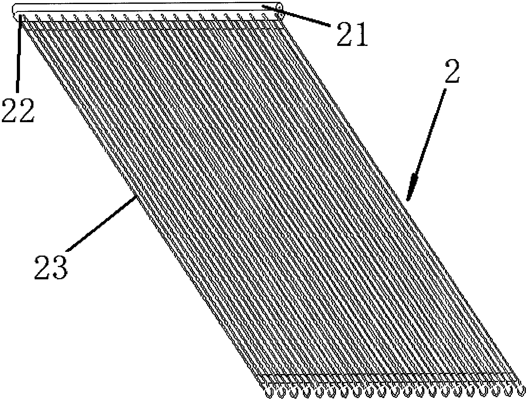
[0024] Such as figure 1 , image 3 , Figure 4 and Figure 6 As shown in the figure, a new type of wall air conditioner terminal is presented in the form of a partition wall, including capillary network pavement module 1, capillary network 2, air supply pipe 3, structural keel 4, decorative panel 5, downwind outlet 6 and installed in The diversion groove 7 for guiding condensed water at the lower end of the capillary network paving module 1, capillary network 2 is laid on the two surfaces of the capillary network paving module 1, and the " The I-shaped structure keel 4 is separated, and the front and rear two decorative panels 5 are fixed on the two symmetrical facades of the "I"-shaped structural keel 4. The main facade of the capillary network paving module 1 and the decorative panel 5 Parallel to each other but not close to each other, forming a cavity 8, the air supply pipe 3 is arranged at the upper end of the cavity 8, and the lower air outlet 6 is arranged at the low...

Embodiment 2

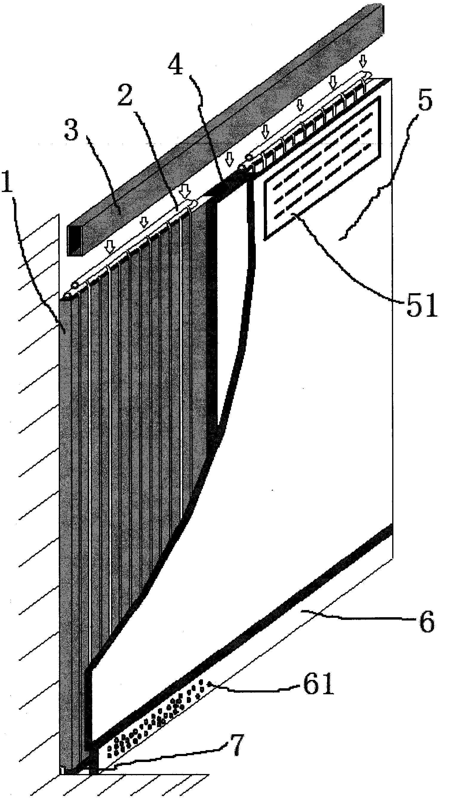
[0028] Such as figure 2 , image 3 , Figure 5 and Figure 6 As shown, a new type of wall air conditioner terminal, this embodiment is mainly applied to the original single-sided wall, including capillary network pavement module 1, capillary network 2, air supply pipe 3, structural keel 4, decorative panel 5, The lower tuyere 6 and the diversion groove 7 installed at the lower end of the capillary network paving module 1 for guiding condensed water, the two surfaces of the capillary network paving module 1 are covered with capillary network 2, and the adjacent two capillary network paving The modules 1 are separated by the "I"-shaped structural keel 4, and the front and rear two decorative panels 5 are fixed on the two symmetrical facades of the "I"-shaped structural keel 4. The capillary network pavement module 1 and decorative The main facades of the panels 5 are parallel to each other but not close to each other, forming a cavity 8, the air supply pipe 3 is set at the u...

Embodiment 3

[0032] Such as figure 1 or figure 2 As shown, the upper end of the veneer 5 is provided with a natural vent 51, and the natural vent 51 can naturally suck in the hot air in the room without mechanical power during cooling. After cooling, the cold air relies on its own gravity to flow from the The downwind outlet 6 is discharged into the room. Others are the same as in Embodiment 1 or 2, and will not be repeated here.


PUM


Abstract

The invention relates to a novel wall air conditioning terminal. The novel wall air conditioning terminal comprises capillary network laying modules 1, a capillary network 2, a blast pipe 3, a structural keel 4, a veneer 5, a lower air inlet 6 and a diversion trench 7 formed in the lower end of the capillary network laying module 1 and used for guiding condensate water and is characterized in that the capillary network 2 is laid on the surface of the capillary network laying modules 1, the adjacent two capillary network laying modules 1 are separated by the structural keel 4; the veneer 5 is fixed on one of facades of the structural keel 4; the main facades of the capillary network laying modules 1 and the veneer are in parallel but not near, so as to define a cavity 8; the blast pipe 3 is arranged at one end of the cavity 8; the lower air inlet 6 is formed in the other end of the cavity 8 to form a whole ventilation system. The novel wall air conditioning terminal is generally combined with various heat pumps and central ventilation systems thereof to achieve the purpose of utilizing the wall to realize the air conditioning function.

Description

technical field [0001] The invention belongs to the technical field of decoration and decoration materials, and relates to indoor heating and cooling technologies, in particular to a novel wall air-conditioning terminal technology for cooling or heating through a capillary network. Background technique [0002] In the prior art, the traditional pavement method of capillary network radiant air conditioner is still the same. First lay the insulation board on the wall or ceiling, then lay the capillary mat on the insulation board, and then smear it with a thickness of about 10mm. The plaster is complex in construction, takes up the height of the floor, and the site is dirty and messy, with heavy humidity; in particular, a complex air humidity adjustment and control system is required, and windows are generally not allowed to be opened during use. Not only the investment is high, but also the energy consumption is high during dehumidification. [0003] At present, there is anot...

Claims


Application Information

Patent Timeline
Patent Type & Authority Applications(China)
IPC IPC(8): F24F1/00F24F13/02F24F13/22F24F13/30
CPCF24F1/0007F24F1/0057F24F13/0227F24F13/30
Inventor 李渊李增清
Owner 李渊
Why Eureka
Try Eureka