Phase-controlled model-based overlay measurement systems and methods

A technology of modeling and imaging system, applied in measurement device, photoengraving process of pattern surface, character and pattern recognition, etc., can solve problems such as large target, unsuitable for future application, poor handling of weak overlapping signals, etc.

Inactive Publication Date: 2015-02-11
JSMSW TECH
View PDF5 Cites 11 Cited by
  • Summary
  • Abstract
  • Description
  • Claims
  • Application Information

AI Technical Summary

Problems solved by technology

However, it has a number of key disadvantages, such as the need for large targets, poor handling of weak overlapping signals, shallow depth of focus, patterns from around the target, and severe effects from imaging system aberrations

Method used


Image

  • Phase-controlled model-based overlay measurement systems and methods
  • Phase-controlled model-based overlay measurement systems and methods
  • Phase-controlled model-based overlay measurement systems and methods

Examples


Embodiment Construction

[0042] A detailed description of the body of the invention is provided below. While example embodiments are described, it should be understood that the present disclosure is not limited to any one embodiment, but rather covers numerous alternatives, modifications, and equivalents, as well as combinations of features from different embodiments.

[0043] Additionally, although numerous specific details are set forth in the following description in order to provide a thorough understanding of the invention in context, some embodiments may be practiced without some or all of these details. Also, for the purpose of clarity, certain technical material that is known in the related art has not been described in detail so as not to unnecessarily obscure the context of the present invention.

[0044] The scope of the patent application as described below is incorporated into the [Detailed Embodiments] and constitutes a part of the [Detailed Embodiments].

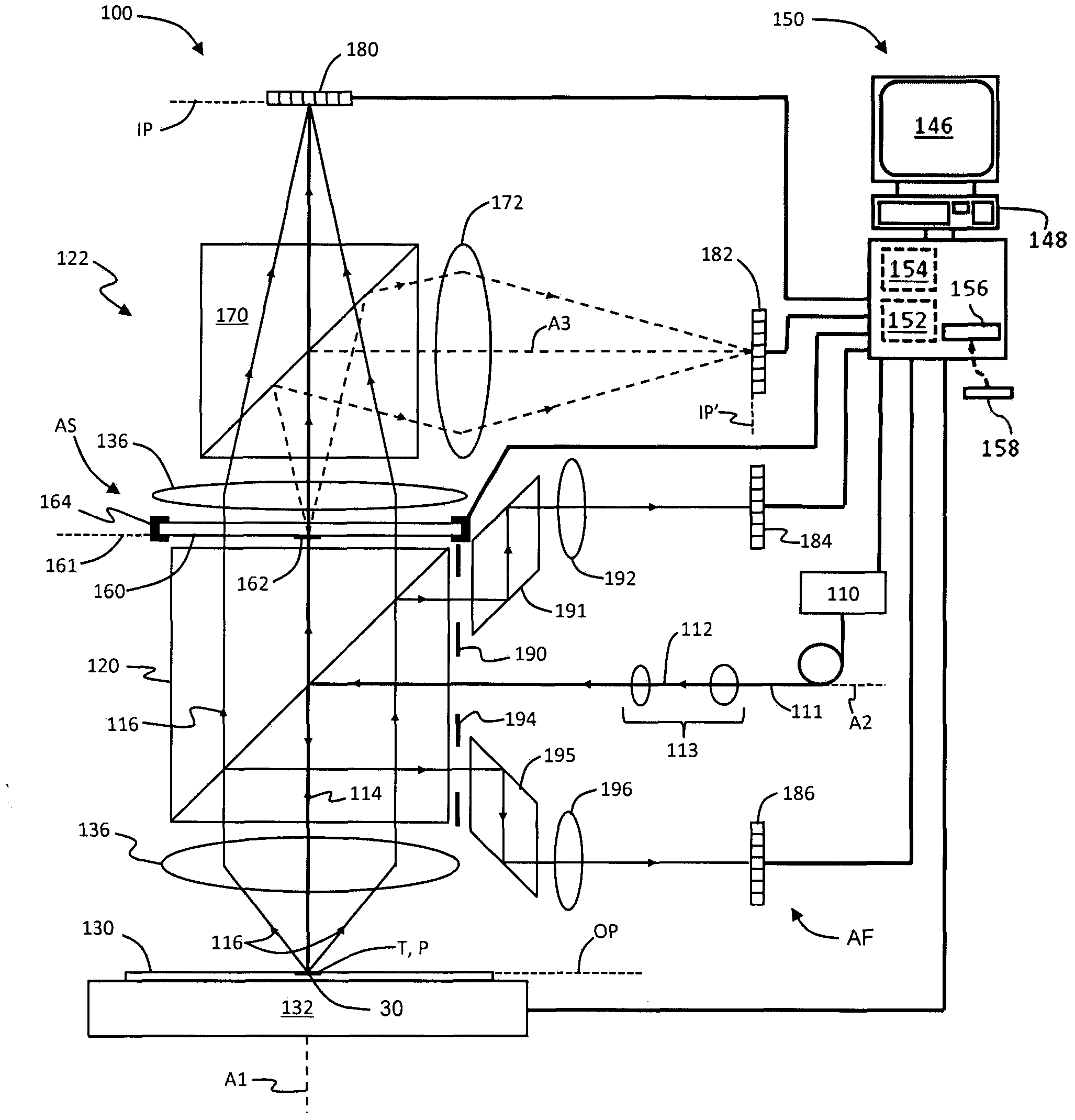
[0045] A general optical over...


PUM


Abstract

Overlay measurement systems and methods are disclosed that control the relative phase between the scattered and specular components of light to amplify weak optical signals before detection. The systems and methods utilize model-based regressional image processing to determine overlay errors accurately even in the presence of inter-pattern interference.

Description

[0001] claim of priority [0002] This application claims priority to US Patent Application Serial No. 61 / 863,469, filed August 8, 2013, which application is incorporated herein by reference. technical field [0003] The present invention relates to an optical overlap measurement system, and in particular to the use of phase control optics for imaging even when the overlapping target is substantially smaller than the target currently in use and surrounded by other patterns and Systems and methods for model-based regression methods for image processing to accurately measure overlay error. [0004] All documents cited herein are hereby incorporated by reference. Background technique [0005] Most finely structured devices (such as integrated circuit chips, microelectromechanical devices, etc.) are made of multiple layers of precisely aligned electrical or mechanical patterns. This pattern is typically formed via multiple high-precision photolithographic steps during fabricat...

Claims


Application Information

Patent Timeline
IPC IPC(8): G06T7/00G06V10/88
CPCG06T7/0004G06K9/6202G06T2207/30148G06T7/0032G06T7/344G03F7/706G06V10/751G06T7/001G01N21/956G03F7/70633G06V10/88
Inventor H·J·郑翁
Owner JSMSW TECH
Why Eureka
Try Eureka