work machinery

A technology of operating machinery and engines, which is applied in earth movers/excavators, construction, etc., and can solve problems such as difficult maintenance operations

Inactive Publication Date: 2016-11-02
YANMAR CO LTD
View PDF5 Cites 0 Cited by
  • Summary
  • Abstract
  • Description
  • Claims
  • Application Information

AI Technical Summary

Problems solved by technology

[0004] However, when the operator performs maintenance work on the radiator, when the coolant is discharged from the radiator to the outside of the engine room, in order to discharge the coolant through the bottom hole below the radiator, it is necessary to drill into the body. It is difficult to carry out maintenance work smoothly

Method used


Image

  • work machinery
  • work machinery
  • work machinery

Examples


Embodiment Construction

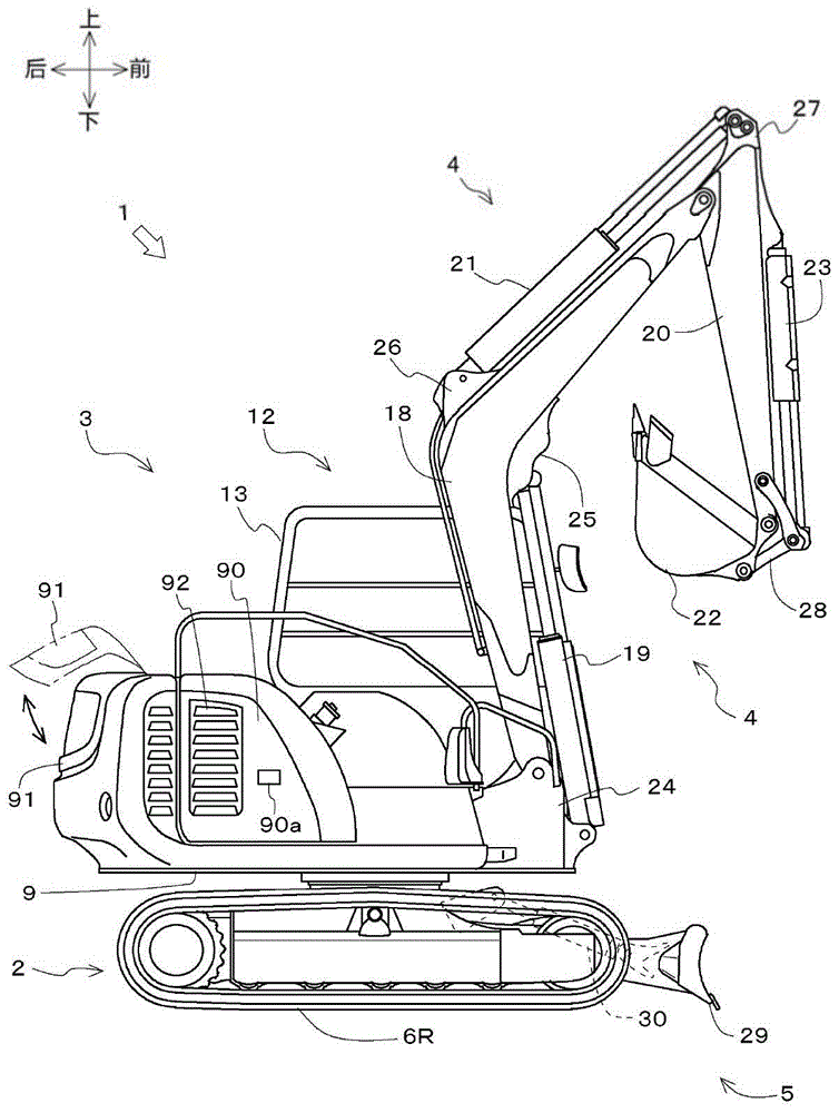
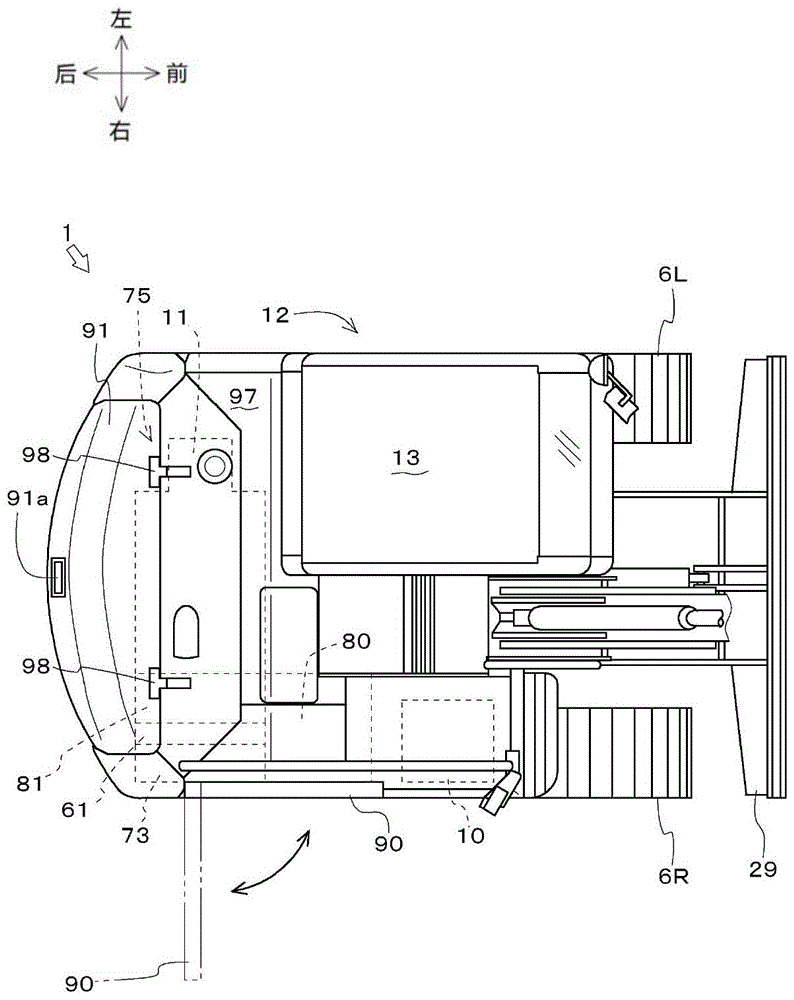
[0032] Hereinafter, the work machine (backhoe 1) will be described with reference to the drawings.

[0033] like figure 1 as well as figure 2 As shown, the backhoe 1 is a rotary working machine. The backhoe excavator 1 includes: a crawler-type traveling device 2; a body 3, which is arranged in the center of the upper part of the crawler-type traveling device 2, and is mounted on the crawler-type traveling device 2 so as to be rotatable left and right; an operating device 4 (boom 18, boom Oil cylinder 19, stick 20, stick cylinder 21, bucket 22, and bucket cylinder 23), are installed on the front part of body 3; bulldozing device 5 (dozer blade 29 and bulldozer cylinder 30), are installed on The front and rear sides of the crawler-type traveling device 2 ; and the control valve device 10 .

[0034] The crawler-type traveling device 2 includes: crawler-type traveling units 6L, 6R arranged as a pair of left and right; and hydraulic actuators (traveling motors) for driving the ...


PUM


Abstract

The purpose of the present invention is to smoothly conduct maintenance work on a heat exchanger without the need to crawl under the machine body to work when draining coolant from the heat exchanger. A side of an engine compartment (75) can be opened and closed by means of a side cover (90) of the engine compartment (75), and a radiator (61) has a drain port (69) for draining the coolant. One end of a drain hose (71) is connected to the drain port (69), and the other end of the drain hose (71) can be pulled outside of the engine compartment (75) by opening the side cover (90).

Description

technical field [0001] The present invention relates to working machines such as hydraulic excavators and backhoes. Background technique [0002] Conventionally, the technology of working machines equipped with heat exchangers (radiators) is well known (for example, Patent Document 1). [0003] Conventionally, in working machines, a bottom cover is disposed below the radiator, and a bottom hole for discharging coolant from the radiator is left in the bottom cover. [0004] However, when the operator performs maintenance work on the radiator, when the coolant is discharged from the radiator to the outside of the engine room, in order to discharge the coolant through the bottom hole below the radiator, it is necessary to drill into the body. It is difficult to carry out maintenance work smoothly because the work is carried out below. [0005] prior art literature [0006] patent documents [0007] Patent Document 1: Japanese Patent Laid-Open No. 2012-36671 Contents of th...

Claims


Application Information

Patent Timeline
Patent Type & Authority Patents(China)
IPC IPC(8): E02F9/00
CPCE02F9/0833E02F9/0866E02F9/0883E02F9/0891
Inventor 小山田保幸河村卓藏永田正夫
Owner YANMAR CO LTD
Why Eureka
Try Eureka