Automatic deal device and system

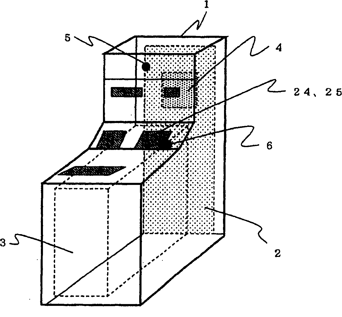
An automatic transaction device and automatic transaction technology, applied in the direction of complete banking system, complete banking system, instrument, etc., can solve the problems of customer injury, difficulty, being caught between the frame and unit 3, etc.

Inactive Publication Date: 2011-02-02
OKI ELECTRIC IND CO LTD
View PDF1 Cites 0 Cited by
  • Summary
  • Abstract
  • Description
  • Claims
  • Application Information

AI Technical Summary

Problems solved by technology

In such a case, sometimes the customer's hand is put into the open position state of the opening 25 due to suddenly retreating from the reception opening 24. When returning to ATM1, the customer's hand is sometimes pinched between the frame and unit 3, causing the customer to be injured
[0009] In addition, in the form of using multiple ATMs side by side, even if the customer is noticed, it is difficult to accurately grasp which ATM the customer is actually using, so if the customer does not operate, pull out the unit 3 , but in fact the customer exists, the same situation as the above-mentioned situation will cause the customer to be injured

Method used


Image

  • Automatic deal device and system
  • Automatic deal device and system
  • Automatic deal device and system

Examples


Embodiment 2

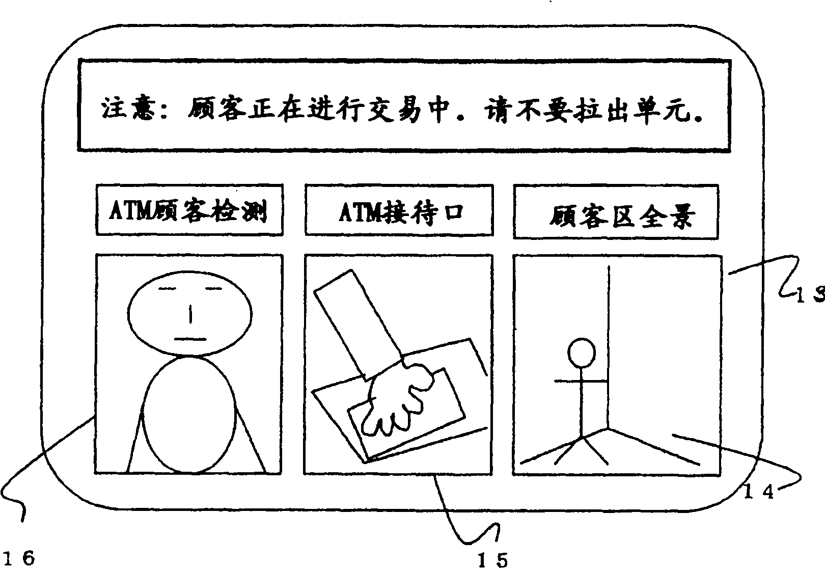
[0039] In Embodiment 2 of the present invention, what illustrated is that under the form that a plurality of ATMs described in Embodiment 1 are arranged side by side, the display unit of one ATM selects the cameras of other ATMs to perform operations on the display unit. displayed situation.

[0040] (constitute)

[0041] The configuration of Embodiment 2 will be described below. Figure 5 It is a state diagram of setting up ATM1 in three adjacent machines. Here, ATM1A-1C is ATM which has the structure completely the same as ATM1 of Example 1. Although only three units are illustrated in this embodiment, the present invention is not limited thereto, and any number of units may be installed.

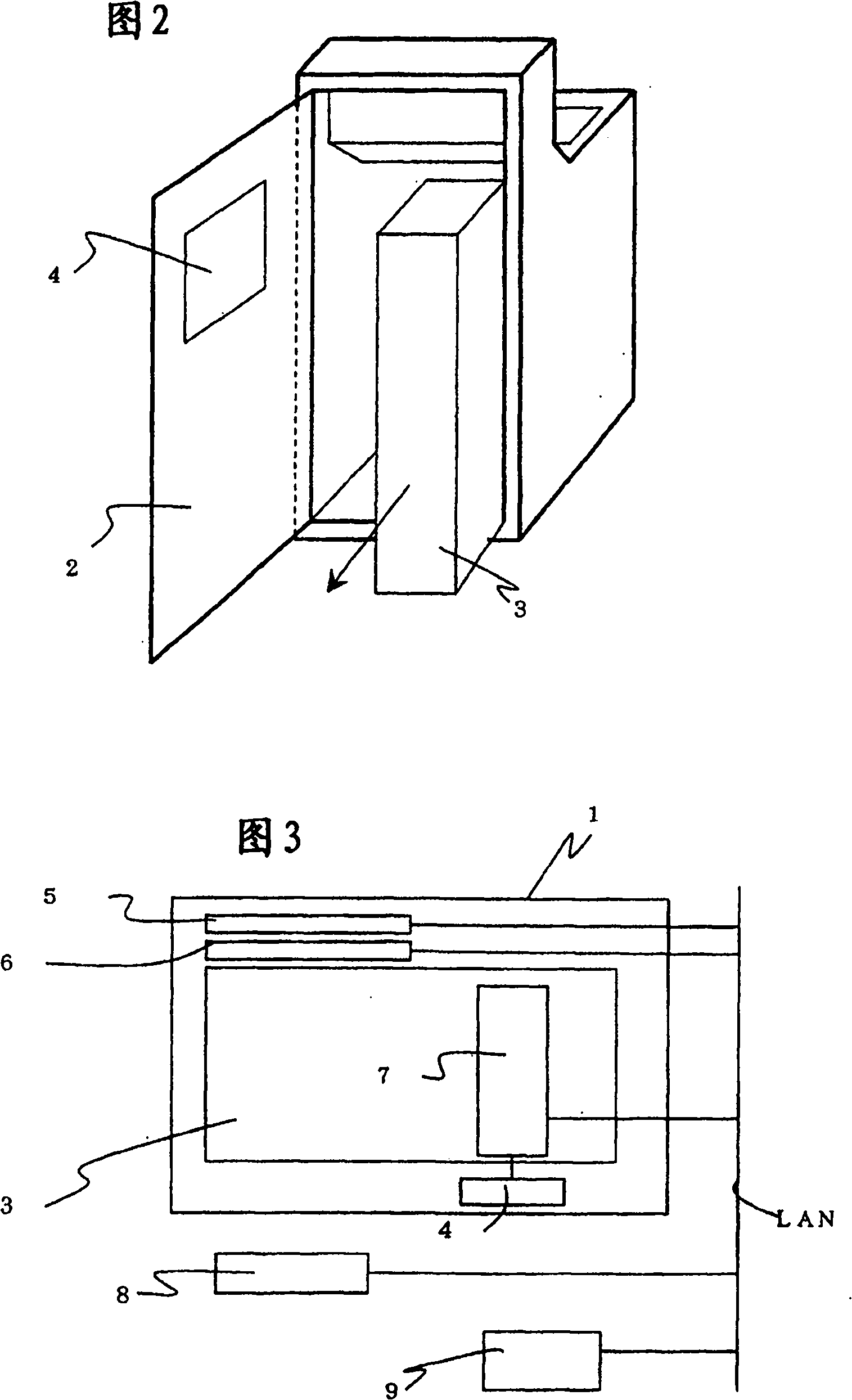
[0042] Figure 7 It is a system configuration diagram of ATM1A-1C. Customer detection cameras 5A to 5C and reception cameras 6A to 6C are installed in the respective ATMs 1A to 1C. Furthermore, corner cameras 8 are provided which capture a panoramic view of the customer area. Each ...

Embodiment 3

[0051] Embodiment 3 of the present invention is based on the image of the customer displayed on the display unit 4 of Embodiment 1. If it is determined that there is a customer based on the displayed image, the unit is fixed on the frame of the ATM so that it cannot be pulled out. the locking mechanism.

[0052] (constitute)

[0053] The configuration of Embodiment 3 will be described below. Figure 10 An overview of the locking mechanism of this embodiment is given. A first lock mechanism 10 is attached to the bottom of the front portion of the unit 3, and a second lock mechanism 12 is attached to the center portion. A lock bolt 11 formed of a metal shaft is attached to a portion facing the frame of the ATM 1 of the first lock mechanism.

[0054] Figure 11 (a) is a structural diagram of the first locking mechanism 10 . 31 is an electromagnet for unlocking the electromagnetic lock lever, which is a structure that can be controlled ON / OFF by the control unit 7 . Electrom...


PUM


Abstract

In order to solve the problem wherein an automatic transaction apparatus, such as a conventional automated teller machine wherein, if an inner unit is drawn out during maintenance work, a hole opens in the position of a customer service window in the front of the apparatus into which a customer inserts his hand, making it likely that when the unit is returned, the customer gets his hand caught inbetween the casing of the apparatus and the unit. A display part is provided on a door at the rear of an ATM, and a camera for verifying customers and a camera for imaging the customer service windoware provided on the body of the ATM. When the unit is drawn out of the ATM, images taken by the cameras are displayed in the display part. Also, a locking mechanism, capable of non-removably locking the unit, is provided at the joint between the casing of the ATM and the unit; when it is determined that a customer is making a transaction according to the camera images, the unit is locked to make the unit non-removable.

Description

technical field [0001] The present invention relates to a maintenance mechanism capable of safely performing maintenance work for automatic transaction devices such as ATMs. Background technique [0002] In the transaction business of financial institutions, the proportion of transactions performed by customers operating automatic transaction devices such as ATMs (Automatic Teller Machines: AUTO TELLER MACHINE) by themselves is increasing. Therefore, by setting up dedicated ATM corners in financial institutions, customers can easily and happily conduct transactions without face-to-face with bank staff or maintenance personnel. [0003] In the above ATM corner, such as Figure 13 As shown, the periphery of ATM1 is shielded by a wall, and the maintenance area and the customer area are set separately so that maintenance personnel do not perform maintenance operations facing customers. ATM1 such as Figure 14 As shown in (a), adopt the built-in unit 3 of device groups such as ...

Claims


Application Information

Patent Timeline
Patent Type & Authority Patents(China)
IPC IPC(8): G07F19/00
Inventor 岩月敬利谷一镰形健太郎登坂由之
Owner OKI ELECTRIC IND CO LTD
Why Eureka
Try Eureka