Leaning mechanism for drawer back plate

A back panel and back panel technology, applied in drawers, applications, home appliances, etc., can solve problems such as side panels cannot be installed and drawers are difficult to install, and achieve the effects of improving integrity, quick disassembly and assembly, and reliable performance

Active Publication Date: 2015-02-18
伍志勇
View PDF5 Cites 4 Cited by
  • Summary
  • Abstract
  • Description
  • Claims
  • Application Information

AI Technical Summary

Problems solved by technology

It is said that the back panel of the drawer is provided with a connecting piece, and the connecting piece is provided with an adjustment device. Relative position adjustment with the side panels and / or connectors; however, the back panel is made of wood and the specifications required for the back panel are very strict, and when the back panel is deformed or does not meet the specifications, the side panels may It cannot be installed on the back panel or there will be a gap between the side panel and the back panel, which will cause difficulties for users when installing the drawer

Method used


Image

  • Leaning mechanism for drawer back plate
  • Leaning mechanism for drawer back plate
  • Leaning mechanism for drawer back plate

Examples


no. 1 example

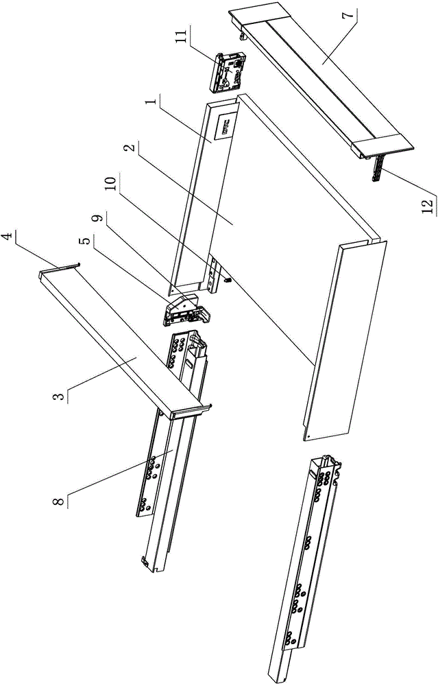
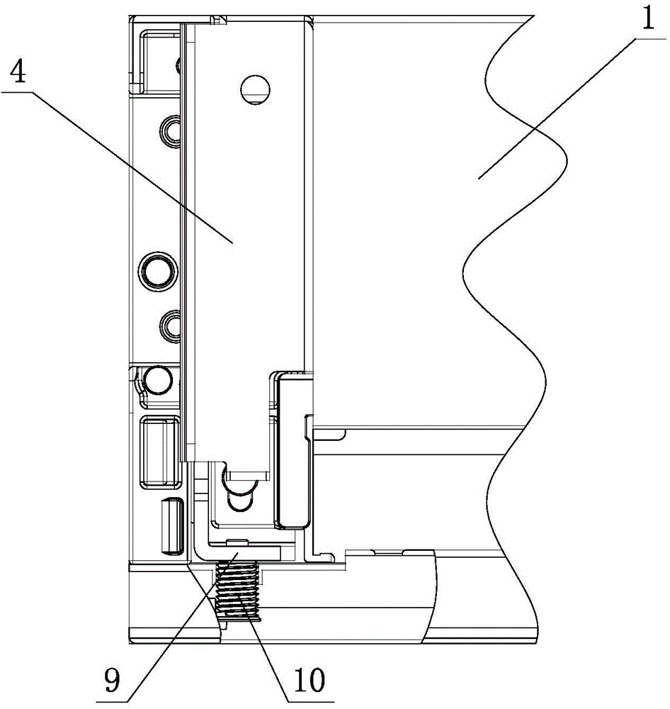
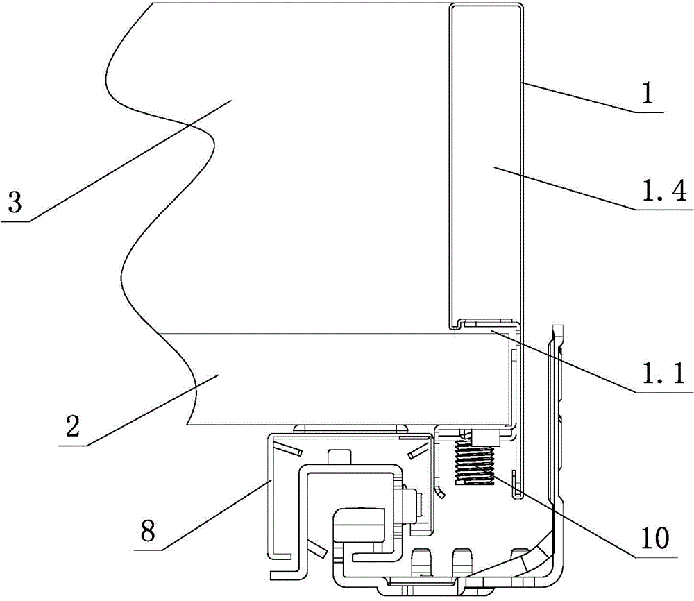
[0040] see Figure 1-11 , which is used for the relying mechanism of the drawer back panel, including side panel 1, bottom panel 2, front panel 7, back panel and slide rail assembly, the back panel is made of wooden material and fastened to the back panel 3 The connecting piece 4 at both ends of the piece 3 is formed, the back panel is connected with the side plate 1 through the connecting piece 4, the side plate 1 is provided with a cavity 1.4, a fixing device is arranged in the cavity 1.4, and a connecting part 5 is arranged on the fixing device , the inner side of the side plate 1 is at least partly vertical, the back plate is connected to the connecting part 5 through the connecting piece 4, and the rear plate 3 is leaned on the inner vertical surface of the side plate 1.

[0041] The back panel is detachably connected to the fixing device and / or the connecting part 5 through the connecting piece 4, and the back panel 3 is elastically connected to the side plate 1 through th...

no. 2 example

[0049] see Figure 12 , Figure 13 , the relying mechanism used for the backboard of the drawer is different from the first embodiment in that: the connecting part 4.1 of the connecting part 4 and the fixed part 4.2 form an inclined angle fit less than 90°, and the rear plate part 3 One side is fixed on the fixing part 4.2, and the other side is supported on the connecting part 4.1, so that an angle B greater than 90° is formed between the rear panel 3 and the inner vertical surface of the side panel 1 to connect.

[0050] Or, the connecting piece 4 is provided with a convex portion 4.5 towards the direction of the rear panel 3, one side of the rear panel 3 is fixed on the fixed portion 4.2, and the other side is supported on the convex portion 4.5, the connection between the rear panel 3 and the connecting piece 4 Form an angle D less than 90° between them, so that the rear plate 3 and the inner vertical surface of the side plate 1 form an angle B greater than 90° to connect...

no. 3 example

[0053] see Figure 14 , Figure 15 , which is used for the relying mechanism on the backboard of the drawer, it is different from the first embodiment in that: the extension part 4.3 of the connector 4 and the bending part 4.4 form an inclined angle E greater than 90° to cooperate, and the connector 4. Through the detachable connection between the extension part 4.3 and the bending part 4.4 and the connecting element 6 of the connecting part 5, an angle B greater than 90° is formed between the rear plate part 3 and the inner vertical surface of the side plate 1.

[0054] Others are not described in the first embodiment.


PUM


Abstract

The invention relates to a leaning mechanism for a drawer back plate. The leaning mechanism comprises side plates, a bottom plate, a front surface plate, a back plate and a slide rail assembly, wherein the back plate consists of a back plate part and a connecting piece, the back plate part is made of wood material, the connecting piece is tightened to the two ends of the back plate part, the back plate is matched and connected with the side plates through the connecting piece, a cavity is formed in each side plate, a fixing device is arranged in the cavities, a connecting part is arranged on the fixing device, at least one part of the inner side of each side plate is vertically arranged, the back plate is connected with the connecting part through the connecting piece, and the back plate part of the back plate is leaned against the vertical surfaces of the inner sides of the side plates. By improving the structure, the leaning mechanism has the characteristics that the structure is simple and reasonable, the property is reliable, the detachment and installation are quick and convenient, the appearance is regular and attractive, the manufacturing cost is low, and the practicality is high.

Description

technical field [0001] The invention relates to a drawer backboard, in particular to a relying mechanism for the drawer backboard. Background technique [0002] Chinese Patent Document No. CN103989332A disclosed on August 20, 2014 an adjustment device for the back panel of a drawer, including a side panel, a bottom panel, a back panel and a slide rail assembly for opening and closing the drawer. There is a rear connecting device for connecting the back board, the back board is made of wood, and its end is provided with a connecting piece, and the connecting piece is detachably joined and / or separated from the rear connecting device; the connecting piece is provided with an adjustment The device, the back panel is arranged on the adjusting device and / or the connecting piece through the fixing unit, and the relative position adjustment between the back panel and the side panel and / or the connecting piece is realized through the adjustment of the adjusting device. It is said t...

Claims


Application Information

Patent Timeline
Patent Type & Authority Applications(China)
IPC IPC(8): A47B88/00
Inventor 伍志勇
Owner 伍志勇
Why Eureka
Try Eureka