Gas-liquid pressurization cylinder

A technology of gas-liquid pressurized cylinder and pneumatic cylinder, which is applied in fluid pressure converters, mechanical equipment, etc., can solve the problems of too much compressed air, low output area efficiency, and too many cylinder blocks, and achieve precise positioning and adjustment, and gas The effect of high source utilization and compact air pressure cavity

Active Publication Date: 2013-10-23
俞祖文
View PDF8 Cites 13 Cited by
  • Summary
  • Abstract
  • Description
  • Claims
  • Application Information

AI Technical Summary

Problems solved by technology

Among them, the side-by-side type is inconvenient to install (such as patent number: 200920051699.9), while the tandem type is too long after series connection (such as patent number: 01262905.7), or the structure is complicated, or the annular oil storage cylinder and the hydraulic booster cylinder are in the same section above, or the output area efficiency is not high (such as patent number: 200520069735.6)
At the same time, both of them have the disadvantage of having many and long cylinder blocks, which consume a lot of compressed air in one action, resulting in low efficiency of air source utilization.

Method used


Image

  • Gas-liquid pressurization cylinder
  • Gas-liquid pressurization cylinder
  • Gas-liquid pressurization cylinder

Examples


Embodiment Construction

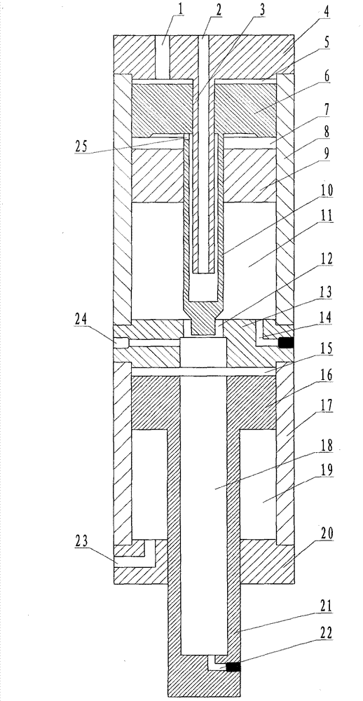
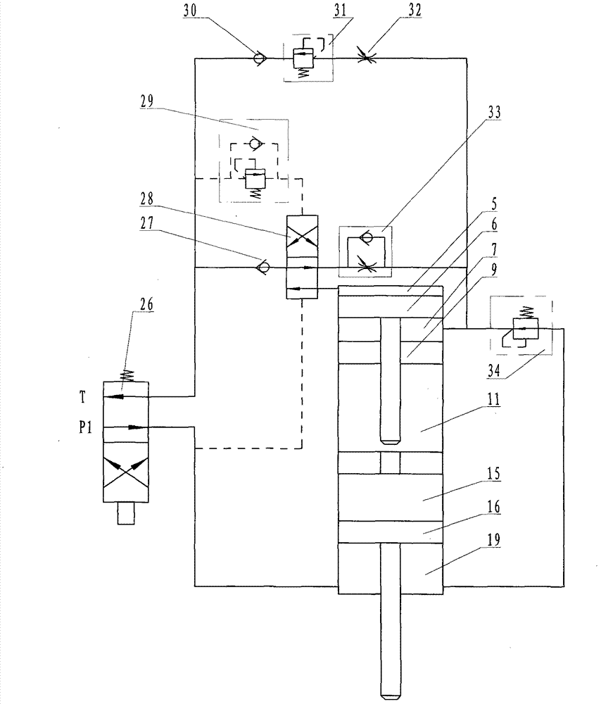
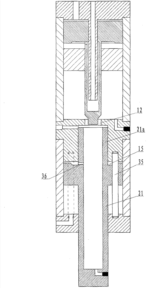
[0020] Attached below Figure 1 ~ Figure 4 Further illustration is made to the principle and structure of the present invention

[0021] Such as figure 1 As shown, the gas-hydraulic booster cylinder composed of pneumatic cylinder 8 and hydraulic cylinder 17 in series is connected and separated by a middle cover 13 between the two cylinders. The other end of the pneumatic cylinder 8 has an upper end cover 4, and the other end of the hydraulic cylinder 17 There is a lower end cover 20. There is a booster piston 6 between the upper end cover 4 and the middle cover 13. A booster air cavity 5 is formed between the upper end cover 4 and the booster piston 6. Between the booster piston 6 and the middle cover 13 There is an air-separating piston 9 with a hole in the middle, and a hollow booster piston rod 10 is arranged on the booster piston 6, and the booster piston rod 10 stretches out from one end of the booster piston 6, and the top of the booster piston rod 10 protruding end is ...


PUM


Abstract

The invention discloses a gas-liquid pressurization cylinder. The gas-liquid pressurization cylinder is formed by the fact that a gas pressure cylinder body and a hydraulic cylinder body are in series connection through a middle cover with a middle hole and are separated into a pressurization gas cavity, a pre-pressing gas cavity, a pre-pressing oil storage cavity, a pressurization oil cavity and a stroke returning gas cavity through an upper end cover with a gas guide pipe, a pressurization piston with a hollow pressurization rod, a gas separation piston, the middle cover with the hole, a working piston and a lower end cover. The pressurization gas cavity, the pre-pressing gas cavity and the stroke returning gas cavity are respectively communicated with an exterior gas circuit through respective connectors, and the working processes of the pre-pressing stroke, the pressurization stroke and the reset stroke can be achieved through the control over the gas circuit. Compared with an existing gas-liquid pressurization cylinder, wherein the existing gas-liquid pressurization cylinder is provided with three or more cylinder bodies, and the cylinder bodies are in parallel connection or in serial connection, the gas-liquid pressurization cylinder has the advantages of being exquisite in structure, convenient to machine and high in use efficiency of a gas source. In addition, the design of the structure of conducting reasonable guiding and preventing rotation is added on an output working piston rod of the cylinder, and the installation and application of subsequent use are simplified.

Description

technical field [0001] The gas-hydraulic pressure actuator to which the present invention belongs, particularly relates to a pressurized actuator through gas-liquid conversion. Background technique [0002] In the mechanical field, most of the mechanism's actions are performed by air pressure or hydraulic pressure as the power source. Among them, air pressure has the advantages of cleanliness and quick action response, while hydraulic pressure has the advantages of incompressibility, stable action, and large output. In order to meet the above requirements at the same time in the same system, it is uneconomical to configure two sets of pressure systems in terms of cost and management. Especially in the occasions where the hydraulic pressure is not used much in the system and it is necessary due to the large output, it is more scientific and reasonable to convert the air pressure to hydraulic pressure to meet the above requirements. Devices for gas-liquid conversion are very ...

Claims


Application Information

Patent Timeline
Patent Type & Authority Applications(China)
IPC IPC(8): F15B3/00
Inventor 俞祖文
Owner 俞祖文
Why Eureka
Try Eureka