Massaging movement of massager

A massager and machine core technology, applied in kneading massage equipment, massage auxiliary products, physical therapy, etc., can solve problems affecting massage effects, massage parts restrictions, etc.

Active Publication Date: 2015-02-18
XIAMEN BIKANG ELECTRONICS
View PDF4 Cites 14 Cited by
  • Summary
  • Abstract
  • Description
  • Claims
  • Application Information

AI Technical Summary

Problems solved by technology

The existing massager only has two massage heads on the left and r...

Method used


Image

  • Massaging movement of massager
  • Massaging movement of massager
  • Massaging movement of massager

Examples


Embodiment 1

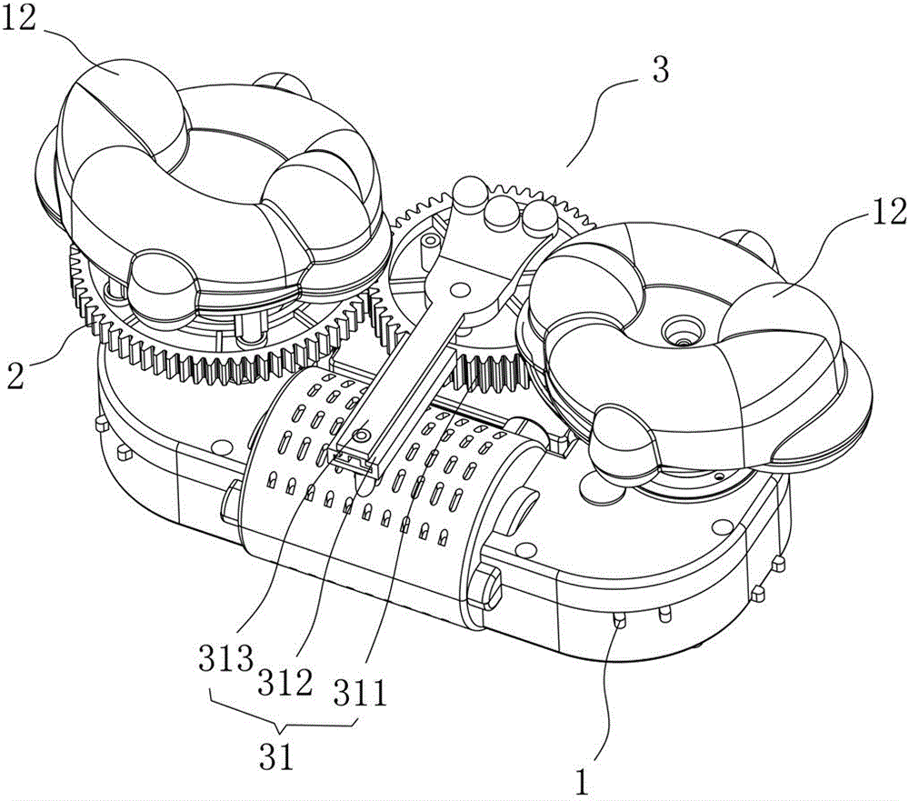
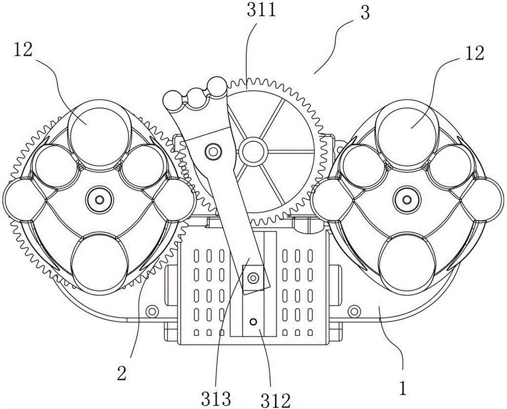
[0028] Example 1: See Figure 1 to Figure 5 As shown, a massage mechanism of a massager includes a main massage mechanism 1 , a transmission part 2 and a push-pull massage mechanism 3 .

[0029] see Figure 1 to Figure 5 As shown, the aforementioned main massage machine core 1 includes a power output assembly 11, and two massage heads 12 connected and linked with the power output assembly 11, and the transmission member 2 is fixed under one massage head 12 and connected with it and linked, and massage The mechanism 3 is located between the two massage heads 12, and the massage mechanism 3 is connected and interlocked with the transmission member 2, thereby forming a massage core structure with a push-pull massage function.

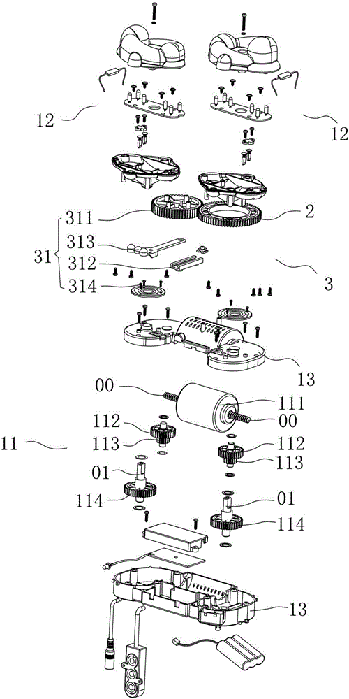
[0030] see Figure 1 to Figure 5 As shown, the core of the aforementioned main massage machine includes a housing 13, a power output assembly 11 and two massage heads 12. The power output assembly 11 is located in the housing 13 and has an output shaft e...

Embodiment 2

[0037] Example 2: Combining Figure 6 As shown, a massage mechanism of a massager includes a main massage mechanism 1 , a transmission part 2 and a push-pull massage mechanism 3 .

[0038] combine Figure 6 As shown, the structure of the aforementioned main massage movement 1 is the same as that in Embodiment 1, and will not be described here again.

[0039] combine Figure 6 As shown, the aforementioned push-pull massage mechanism 3 is located outside two or any one of the massage heads in the main massage mechanism, thereby forming a massage structure for the waist of the human body.

[0040] combine Figure 6 As shown, the aforementioned transmission member 2 is one or two and is located below the massage head 13, and is fixed separately or integrally with the massage head 13, and the transmission member 2 is a transmission gear, and the push-pull massage mechanism 3 is realized by the transmission gear. Driven by the main massage movement 1, the massage is realized.

...

Embodiment 3

[0045] Example 3: Binding Figure 7 As shown, a massage mechanism of a massager includes a main massage mechanism 1 , a transmission part 2 and a push-pull massage mechanism 3 .

[0046] combine Figure 7 As shown, the structure of the aforementioned main massage movement 1 is the same as that in Embodiment 1, and will not be described here again.

[0047] combine Figure 7 As shown, the aforementioned transmission member 2 is one or two and is located below the massage head 13, and is fixed separately or integrally with the massage head 13, and the transmission member 2 is a transmission gear, and the push-pull massage mechanism 3 is realized by the transmission gear. Driven by the main massage movement 1, the massage is realized.

[0048] combine Figure 7 As shown, the aforementioned push-pull massage mechanism 3 includes at least two groups of massage groups 31, and each group of massage groups is respectively located between the two massage heads in the main massage m...


PUM


Abstract

The invention discloses a massaging movement of a massager. The massaging movement comprises a main massaging movement, a transmission piece and push-pull massaging mechanisms, wherein the main massaging movement comprises a power output assembly and two massaging heads connected and linked with the power output assembly; the transmission piece is fixed below one massaging head and is connected and linked with the massaging head; the push-pull massaging mechanisms are positioned between the two massaging heads and are connected and linked with the transmission piece; therefore the massaging movement structure with a push-pull massaging function is formed. The structures of the push-pull massaging mechanisms are additionally arranged on the massaging movement; three small massaging heads at the top ends of the push-pull massaging mechanisms are used for massaging the back side of the head and the middle part of the cervical vertebra, so that a better massaging effect is achieved; meanwhile, if the movement is designed to be a massaging waist rest, two rotating malaxation massaging heads are used for massaging the waist, and the three push-pull massaging mechanisms are used for massaging the back.

Description

technical field [0001] The invention relates to a massage movement of a massager, which belongs to the technical field of massage equipment according to the International Patent Classification (IPC). Background technique [0002] After exercise or on sore parts of the body, perform physical therapy massage to relax muscles and tendons, promote blood circulation, and restore to normal. Among the common massage appliances, the massage appliances for the neck and back are the most commonly used and the most convenient to use. The neck, back and other parts of the human body have unique physiological curves, and there will be relatively high requirements for the parts to be massaged. The existing massager only has two left and right massage heads, and the position to be massaged is limited, which affects the massage effect. [0003] Thus, the inventor considers improving the existing massager structure, and this case arises thus. Contents of the invention [0004] Aiming at...

Claims


Application Information

Patent Timeline
IPC IPC(8): A61H7/00
Inventor 蔡加信
Owner XIAMEN BIKANG ELECTRONICS
Why Eureka
Try Eureka