Shaft brake trundle

A technology of caster and shaft brake, which is applied in the field of shaft brake casters to achieve better braking effect and ideal effect

Inactive Publication Date: 2015-02-18
平湖市三得力脚轮制造股份有限公司
View PDF5 Cites 1 Cited by
  • Summary
  • Abstract
  • Description
  • Claims
  • Application Information

AI Technical Summary

Problems solved by technology

[0004] Aiming at the existing problems, the present invention designs a shaft brake caster, which changes the original braking method and changes the braking method to an axial compression stop for the rollers, so as to solve the disadvantages of the existing braking device

Method used


Image

  • Shaft brake trundle
  • Shaft brake trundle
  • Shaft brake trundle

Examples


Embodiment Construction

[0013] The present invention will be further described below with reference to the drawings and embodiments.

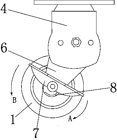
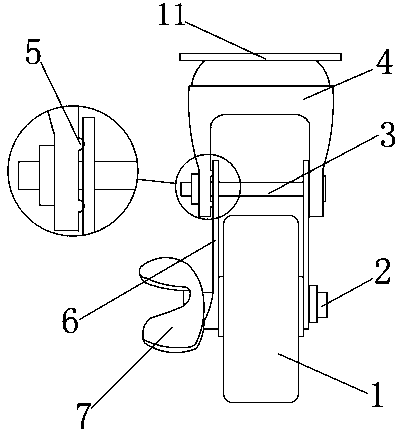
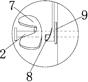
[0014] As shown in Figures 1, 2, 3 and 4: The present invention includes a mounting plate 11, a roller 1 and a roller bracket. The roller bracket includes two side plates 6 and a mounting bracket 4. The two side plates 6 are mounted on the axle 2 On both sides of the roller 1, there is a brake pedal 7 on the outside of the side plate 6. The contact surface of the side plate 6 with the brake pedal 7 is provided with a stop shoulder 8 integrated with the side plate 4, and the upper end of the side plate 6 is fixed by bolts 3. A mounting bracket 4 is connected. The mounting bracket 4 is provided with a circular protrusion 5 on the contact surface with the side plate 6, and the side plate 6 is correspondingly provided with a circular groove 10. The stop shoulder 8 has a gradually decreasing slope structure from the highest point to the lowest point. A friction plate 9 is p...


PUM


Abstract

The invention relates to a shaft brake trundle. A roller bracket comprises two side plates and a mounting bracket, wherein two side plates are mounted on two sides of a roller through roller shafts; brake pedals are arranged on the outer sides of the side plates; locking shoulders which are integrally connected with the side plates are arranged on the contact surfaces of the edges of the side plates and the brake pedals; a mounting bracket is fixedly connected to the upper ends of the side plate through bolts. A conventional brake mode that a vehicle is stopped by virtue of the friction between brake pads and the roller is changed into a brake mode that the rollers are axially pressed by pedals, so that not only is the brake effect relatively ideal, but also the defect of friction of the brake pads and the roller is avoided; as a device which is capable of adjusting the angle is designed between the mounting bracket and the roller, the height of the trundle is changed, and the roller is relatively flexible and convenient when being used.

Description

Technical field [0001] The invention relates to a caster, in particular to an axle brake caster. Background technique [0002] The role of the caster brake refers to when the caster is in a stationary state, the object to be worked needs to be positioned. The auxiliary component is installed to lock the caster. The brake device of the existing caster is generally installed on the upper end of the roller, and the brake device is generally braked. The pads rub against the rollers to stop the operation. However, with such a braking method, after the rollers are used for a long time, as the rollers wear out, the rollers and the brake pads will not have sufficient contact, which directly affects the braking effect of the casters. [0003] Secondly, in the design of general casters, the height of the casters is not adjustable, and their flexibility is limited when used with carts. Summary of the invention [0004] In view of the existing problems, the present invention designs an axle br...

Claims


Application Information

Patent Timeline
Patent Type & Authority Applications(China)
IPC IPC(8): B60B33/00
Inventor 张静芳
Owner 平湖市三得力脚轮制造股份有限公司
Why Eureka
Try Eureka