Fiber optic cable twist test equipment

A torsion test and equipment technology, applied in the direction of applying repeated force/pulsation force to test the strength of materials, measuring devices, instruments, etc., can solve the problems of large heat generation and burning of the motor, and achieve low heat generation, flexible and convenient use, and movement reliable effect

Inactive Publication Date: 2010-04-28
ZHENGZHOU SHIJIA COMM TECH
View PDF0 Cites 27 Cited by
  • Summary
  • Abstract
  • Description
  • Claims
  • Application Information

AI Technical Summary

Problems solved by technology

[0006] The object of the present invention is to provide a kind of optical cable torsion test equipment, to solve the problem that the optical cable torsion test equipment in the prior art controls the forward rotation and reverse rotation of the motor through the control part, so as to realize the twist test of the optical cable. Rotation will cause the motor to burn out due to too much heat

Method used


Image

  • Fiber optic cable twist test equipment
  • Fiber optic cable twist test equipment
  • Fiber optic cable twist test equipment

Examples


Embodiment Construction

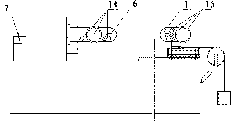
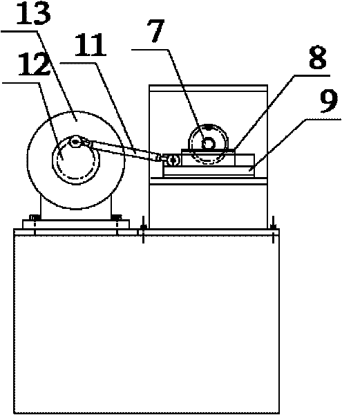
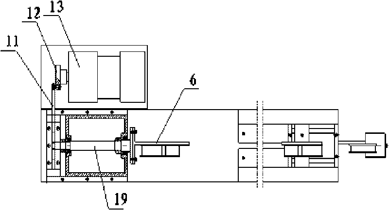
[0022] exist figure 1 , figure 2 , image 3 , Figure 4 , Figure 5 Among them, a kind of optical cable torsion test equipment, comprises frame, is provided with motor 13 on the frame, is provided with the motor turntable 12 that acts as crank on the output shaft of motor 13, and one end of connecting rod 11 is hinged on the disk surface of motor turntable 12, The other end of the connecting rod 11 is hinged with one end of the toothed slider 8, the toothed slider 8 is slidably installed on the frame through the linear bearing 9, the gear 7 is rotated and assembled on the frame through its rotating shaft 19, the gear 7 and the toothed The slider 8 is meshed for transmission, and one end of the rotating shaft 19 of the gear 7 is fixedly provided with a torsion arm 6, the end surface of the torsion arm 6 is fixedly provided with a first clamping device 14, and the slider of the frame is provided with a second clamping device 15.

[0023] exist Figure 6 and Figure 7 Amo...


PUM


Abstract

The invention relates to fiber optical cable twist test equipment. A transmission device of the fiber optical cable twist test equipment comprises a crank-slider mechanism; a slider of the crank-slider mechanism is a stick-shaped slider, and one side of the stick-shaped slider is provided with a drive gear; the toothed slider is engaged with a gear which is rotationally assembled on a machine frame to form a gear rack transmission device; and a twist arm of the fiber optical cable twist test equipment is fixed on a rotating shaft of the gear, and a rotating centre line of the twist arm and a centre line of the rotating shaft of the gear are collinear. A motor drives a crank of the crank-slider mechanism to rotate, the crank drives a connecting rod to perform planar motion, and the connecting rod drives the slider to perform reciprocating linear motion; the slider drives the gear to rotate reciprocally by the drive gear on the slider, and with the reciprocating rotation of the gear, the twist arm which is fixed at one end of the rotating shaft of the gear outputs rotation and twists and drives a fiber optical cable clamed on the twist arm to twist. The fiber optical cable twist test equipment has the advantages that: the structure is simple; the movement is reliable; and the twist arm of the motor can be twisted without rotating forward and backward.

Description

technical field [0001] The invention relates to an optical cable torsion test device. Background technique [0002] With the launch of 3G (3rd generation mobile communications) and FTTH (fiber-to-the-home), with the vigorous development of access networks and customer premises networks, and with the continuous decline in the price of optical receiving devices, the market for indoor optical cables has steadily expanded year by year. Indoor optical cables are thin and soft, easy to install, weak in mechanical strength, and narrow in temperature range. Compared with outdoor optical cables, the requirements for mechanical properties such as tensile strength, lateral pressure resistance, and impact resistance are lower. However, the indoor space is small, there are many turns, and the probability of torsion is high, so the requirements for the repeated torsion performance of indoor optical cables are higher. In order to make indoor optical cables suitable for normal laying in v...

Claims


Application Information

Patent Timeline
Patent Type & Authority Applications(China)
IPC IPC(8): G01N3/26G01N3/32G01N3/02G01N3/04
Inventor 李然山
Owner ZHENGZHOU SHIJIA COMM TECH
Why Eureka
Try Eureka