Unlock instant, AI-driven research and patent intelligence for your innovation.

Injector High Speed ​​Solenoid Valve

A high-speed solenoid valve, solenoid valve technology, applied in the direction of fuel injection devices, machines/engines, charging systems, etc., can solve the problem of inability to quickly and effectively adjust the spring force of the solenoid valve, weak axial guidance of the solenoid valve needle, and replacement of parts Time-wasting and other problems, to achieve the effect of not easy to bend, easy to install and replace, and reduce quality

Active Publication Date: 2019-05-31
钧风电控科技(大连)有限责任公司
View PDF6 Cites 0 Cited by
  • Summary
  • Abstract
  • Description
  • Claims
  • Application Information

AI Technical Summary

Problems solved by technology

The existing high-speed solenoid valve adopts the split structure of the armature and the solenoid valve needle. The solenoid valve needle adopts the downward guiding mode, and the axial guiding effect of the solenoid valve needle is weak; the number of coil turns is large, the heat dissipation is large, and the heat radiation intensity is high. The cost is high; the spring force system of the solenoid valve and the solenoid valve assembly are an integral system. When adjusting the spring force of the solenoid valve, the solenoid valve needs to be disassembled as a whole, which cannot quickly and effectively adjust the spring force of the solenoid valve, resulting in a waste of time for parts replacement. The spring force system is set on the stationary parts, and a large spring force of the solenoid valve is required to ensure the sealing performance of the injector when the injector is closed. Large tightening torque will easily lead to deformation of the solenoid valve parts; the stroke adjustment of the solenoid valve armature needs to disassemble the solenoid valve as a whole Parts can only be adjusted, which complicates the replacement of parts and causes a waste of time; if a fault occurs and it is inconvenient to replace, the overall replacement will cause a lot of waste, reduce the assembly pass rate, and increase the production cost of the product

Method used


Image

  • Injector High Speed ​​Solenoid Valve
  • Injector High Speed ​​Solenoid Valve
  • Injector High Speed ​​Solenoid Valve

Examples


Embodiment Construction

[0037] The present invention will be further described below in conjunction with the accompanying drawings.

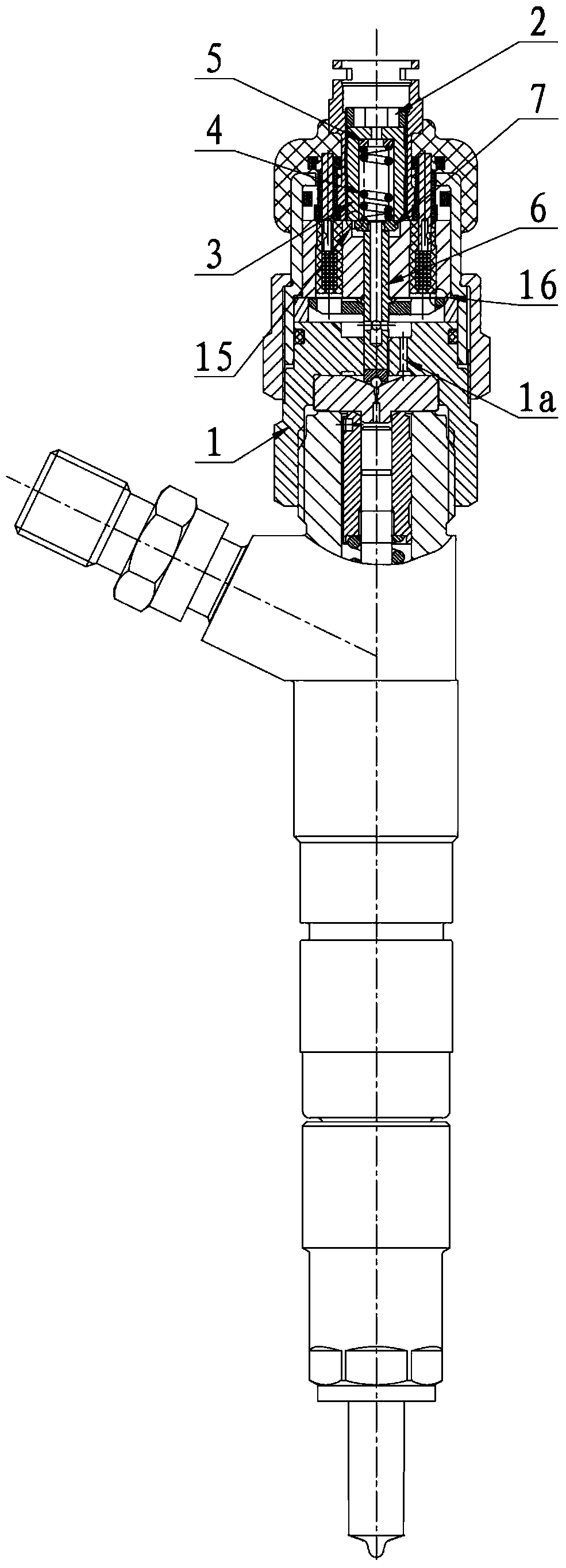
[0038] Such as Figure 1-4 As shown, the high-speed solenoid valve of the fuel injector of the present invention is installed on the upper part of the fuel injector body through the connecting screw sleeve 1, including the fastening screw sleeve 2, the solenoid valve spring sleeve 3, the solenoid valve spring 4, the pressure adjustment washer 5, and the solenoid valve Needle assembly 6, magnetic core part and gap adjustment washer 7; said magnetic core part includes coupling nut 8, solenoid valve tight cap 9, positioning pin 10, magnetic head O-shaped sealing ring 11, magnetic head 12, magnetic isolation pad 13, magnetic core 14. Lead wire 17, coil 18 and pin 19; weld the wound coil 18 and the lead wire 17 firmly as a whole, place it on the coil frame 22, and insert it into the magnetic core 14 for injection molding; the magnetic head 12 is placed on the magnetic The ...


PUM


Abstract

The invention discloses a high-speed electromagnetic valve for an oil sprayer. The high-speed electromagnetic valve comprises a connecting threaded sleeve, a fastening threaded sleeve, an electromagnetic valve spring sleeve, an electromagnetic valve spring, a pressure adjusting washer, an electromagnetic valve needle assembly, a magnetic core part and a clearance adjusting washer, wherein the electromagnetic valve needle assembly is formed through welding an electromagnetic valve needle and an armature into a whole, and the magnetic core part is formed through injection molding of a magnetic core, a magnetic head, a magnetic isolating pad, a pin, a lead, a linkage nut, an electromagnetic valve nut and the like; the electromagnetic valve needle assembly is inserted into the central hole of a magnetic core part and is paired with the magnetic core part in a clearance fit manner; the clearance adjusting washer is arranged at the upper end of the electromagnetic valve needle assembly, the electromagnetic valve spring sleeve is arranged in the central hole of the magnetic head, the electromagnetic valve spring is arranged in the electromagnetic valve spring sleeve, the lower end of the electromagnetic valve spring is abutted with the clearance adjusting washer, the upper end of the electromagnetic valve spring is positioned by the pressure adjusting washer, and the electromagnetic valve spring sleeve is fastened in the magnetic core part by the fastening threaded sleeve. The oil sprayer high-speed electromagnetic valve is simple in structure and convenient to mount.

Description

technical field [0001] The invention relates to the field of high-pressure injection systems of automobile diesel engines, in particular to a high-speed electromagnetic valve for high-pressure common rail injectors. Background technique [0002] In recent years, with the increasingly stringent requirements of emission regulations and the increasing shortage of petroleum energy, the emission standards for diesel engines and the technical requirements for engines have become more and more stringent. But diesel engine emission control is a difficult point. In order to meet the emission standards, the advanced fuel injection system of diesel engines - high pressure common rail technology has become the focus of attention of the industry. [0003] The high-pressure common rail injection system of diesel engine realizes the separation of pressure build-up and injection process, so that the control process is more flexible, and it can more accurately realize the precise control of...

Claims


Application Information

Patent Timeline
Patent Type & Authority Patents(China)
IPC IPC(8): F02M51/06
Inventor 臧广辉李波解芳左照伟戴宏伟杨建鑫
Owner 钧风电控科技(大连)有限责任公司