
A double-acting pneumatic switch

A technology of double-acting air-operated switch and drive seat, which is applied in the directions of engine components, valve details, valve operation/release devices, etc., can solve the problems of high maintenance cost, complicated wiring, and inability to apply safety requirements, and achieves simple structure, The effect of easy operation and use, strong practicability and marketing value

Active Publication Date: 2016-11-23
许环繁
View PDF7 Cites 0 Cited by
  • Summary
  • Abstract
  • Description
  • Claims
  • Application Information

AI Technical Summary

Problems solved by technology

[0002] With the advancement of science and technology, people pay more and more attention to industrial safety issues. In the actual safety production process, there are mainly two types of switches commonly used: pneumatic control switches and electric control switches; among them, electric control switches mainly have complicated wiring. , high leakage risk, high maintenance cost and other defects, which make it unfavorable for safe production; most of the existing pneumatic control switches are single-control switches and due to unreasonable structural design, they cannot be used in applications with high safety requirements. place

Method used


Image

  • A double-acting pneumatic switch
  • A double-acting pneumatic switch
  • A double-acting pneumatic switch

Examples


Embodiment Construction

[0026] The embodiments of the present invention will be described in detail below with reference to the accompanying drawings, but the present invention can be implemented in many different ways defined and covered by the claims.

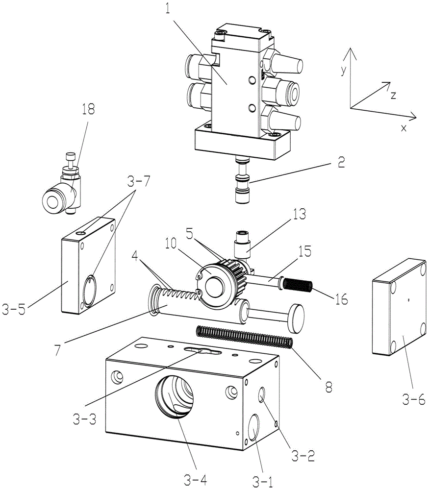
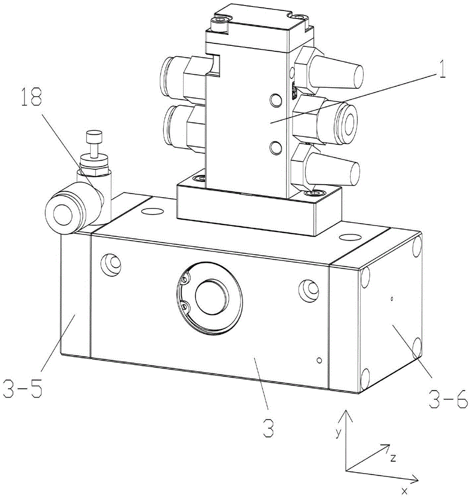
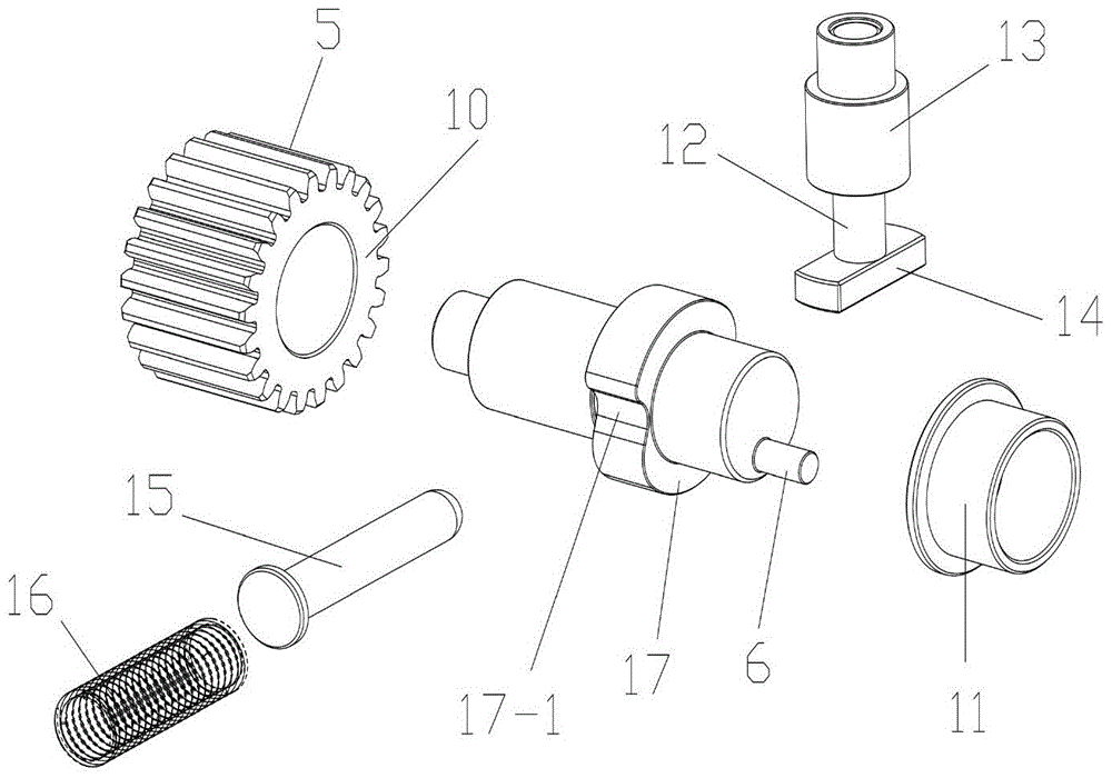
[0027] Such as Figure 1 to Figure 6 As shown, a double-acting pneumatic switch provided by this embodiment includes a valve body 1, and a valve core 2 for realizing the opening or closing of the valve body is arranged in the valve body 1, and it also includes a driving seat 3. 3 is provided with a piston group used as a power source, a guide wheel group as an intermediate transmission link, and a drive rod group used to drive the valve core 2 to move; wherein, the piston group is arranged in the X direction relative to the drive seat 3, and the guide wheel group Relative to the driving seat 3, it is arranged in the Z direction, and the driving rod group is arranged in the Y direction relative to the driving seat 3; at the same time, several tooth g...


PUM


Abstract

The invention relates to the technical field of design and manufacture of valves, and in particular relates to a double-acting gas-controlled switch. The double-acting gas-controlled switch comprises a valve body and a driving base, wherein a piston group, a guide wheel group and a driving rod group are arranged in the driving base; the piston is arranged in an X direction relative to the driving base; the guide wheel group is arranged in a Z direction relative to the driving base; the driving rod group is arranged in a Y direction relative to the driving base; a plurality of tooth sockets are arranged on the piston group; racks meshed with the tooth sockets are arranged at the tail end of the guide wheel group; an eccentric shaft which resists against the tail end of the driving rod group is arranged at the head end of the guide wheel group; the head end of the driving rod group is connected with a valve core; the guide wheel group is driven by the piston group to do rotary motion along the X direction; the driving rod group is controlled by the guide wheel group by virtue of the eccentric shaft to do Y-directional feed motion; the driving rod group is used for controlling the opening or closing of the valve body by virtue of a valve core. According to the double-acting gas-controlled switch, the opening or closing of the valve body is realized by using a lead screw driving principle, so that the effect of accurate control is realized; meanwhile, the supply of the power is realized by utilizing the principle of a piston, and a hardware condition is created for manual control and automation pneumatic control.

Description

technical field [0001] The invention relates to the technical field of valve design and manufacture, in particular to a double-acting air control switch. Background technique [0002] With the advancement of science and technology, people pay more and more attention to industrial safety issues. In the actual safety production process, there are mainly two types of switches commonly used: pneumatic control switches and electric control switches; among them, electric control switches mainly have complicated wiring. , high leakage risk, high maintenance cost and other defects, which make it unfavorable for safe production; most of the existing pneumatic control switches are single-control switches and due to unreasonable structural design, they cannot be used in applications with high safety requirements. place. [0003] Therefore, it is necessary to propose an improvement scheme to the existing pneumatic switch to improve its safety performance and ensure the personal safety ...

Claims


Application Information

Patent Timeline
Patent Type & Authority Patents(China)
IPC IPC(8): F16K31/122
CPCF16K31/143F16K31/54
Inventor 许环繁
Owner 许环繁
Learn More