
Energy-saving air conditioner cooling system

A cooling system, energy-saving technology, applied in air-conditioning systems, heating and ventilation control systems, heating and ventilation safety systems, etc., can solve problems affecting laboratory operations, low air quality, and condensation at air supply outlets. Condensation at the air supply port, simple and reasonable structure, no condensation effect

Inactive Publication Date: 2015-12-30
ZHONGSHAN GREENTA ELECTRONICS TECH
View PDF8 Cites 11 Cited by
  • Summary
  • Abstract
  • Description
  • Claims
  • Application Information

AI Technical Summary

Problems solved by technology

[0002] At present, in the southern high-humidity area, most laboratories or computer rooms are still designed according to the traditional way of thinking and design. Like other buildings, they are designed as general-purpose ordinary air-conditioning systems, such as ordinary air or water-cooled chillers plus terminal fan coils. The central air-conditioning system uses chilled water at 7°C to 12°C to exchange heat with air to obtain cold air from the air conditioner to cool the room, which causes the following major disadvantages: 1) Low system operation efficiency and high energy consumption; 2) In the machine room The accuracy of temperature and humidity cannot be precisely controlled and adjusted, and it cannot really meet the working characteristics of the laboratory or computer room. The air supply, exhaust, and room negative pressure are not adjusted and controlled, and the air quality is not high; 3) In a high-humidity environment, the air supply port The phenomenon of dew is serious, causing water immersion and even affecting the operation of the laboratory

Method used


Image

  • Energy-saving air conditioner cooling system
  • Energy-saving air conditioner cooling system

Examples


Embodiment Construction

[0019] The present invention will be further described below in conjunction with the accompanying drawings and embodiments.

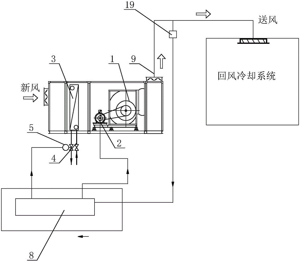
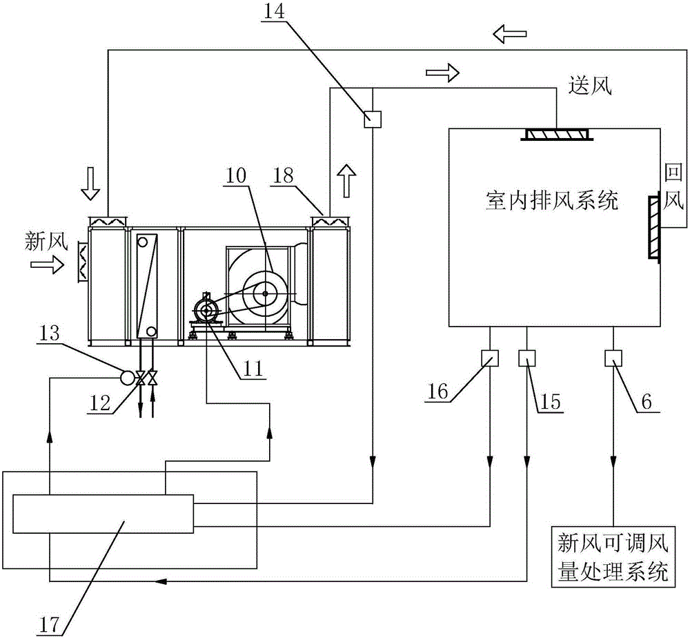
[0020] see Figure 1-Figure 2 , the energy-saving air-conditioning cooling system includes a fresh air adjustable air volume processing system, a return air cooling system and an indoor exhaust system connected in sequence to form an air supply channel, wherein the indoor exhaust system and the return air cooling system are also connected with a return air channel , which is characterized in that the fresh air adjustable air volume processing system is respectively equipped with an outlet air temperature / humidity detection and processing unit and a pressure difference detection and processing unit, and the return air cooling system is respectively equipped with a supply air temperature detection and processing unit, and an indoor temperature detection unit. And processing unit, indoor humidity detection and processing unit; among them, the air outlet te...


PUM


Abstract

The invention relates to an energy-saving air conditioner cooling system which comprises a fresh air adjustable-air-quantity treatment system, a return air cooling system and an indoor exhaust system which are sequentially communicated to form a blast channel, wherein the indoor exhaust system and return air cooling system are also communicated with a return air channel; the fresh air adjustable-air-quantity treatment system is respectively provided with an outlet air temperature / humidity detection and processing unit and a pressure difference detection and processing unit; the return air cooling system is respectively provided with a blast temperature detection and processing unit, an indoor temperature detection and processing unit and an indoor humidity detection and processing unit; the outlet air temperature / humidity detection and processing unit is arranged on the return air cooling system; and the pressure difference detection and processing unit, blast temperature detection and processing unit, indoor temperature detection and processing unit and indoor humidity detection and processing unit are respectively arranged on the indoor exhaust system. The energy-saving air conditioner cooling system has the characteristics of simple and reasonable structure and low operating cost, and does not generate dew.

Description

technical field [0001] The invention relates to an air conditioner cooling system, in particular to an energy-saving air conditioner cooling system. Background technique [0002] At present, in the southern high-humidity area, most laboratories or computer rooms are still designed according to the traditional way of thinking and design. Like other buildings, they are designed as general-purpose ordinary air-conditioning systems, such as ordinary air or water-cooled chillers plus terminal fan coils. The central air-conditioning system uses chilled water at 7°C to 12°C to exchange heat with air to obtain cold air from the air conditioner to cool the room, which causes the following major disadvantages: 1) Low system operation efficiency and high energy consumption; 2) In the machine room The accuracy of temperature and humidity cannot be precisely controlled and adjusted, and it cannot really meet the working characteristics of the laboratory or computer room. The air supply, ...

Claims


Application Information

Patent Timeline
Patent Type & Authority Applications(China)
IPC IPC(8): F24F1/00F24F11/02
CPCF24F1/00
Inventor 黄亚宾
Owner ZHONGSHAN GREENTA ELECTRONICS TECH
Learn More