
Current pulse restraining power drive circuit

A power drive circuit and current suppression technology, which is applied in the direction of electrical components, control systems, motor control, etc., can solve the problems of power supply influence, interference and damage of other components in the equipment, and achieve the effect of suppressing current pulses

Active Publication Date: 2015-02-18
PUYA SEMICON SHANGHAI CO LTD
View PDF3 Cites 0 Cited by
  • Summary
  • Abstract
  • Description
  • Claims
  • Application Information

AI Technical Summary

Problems solved by technology

[0002] Small motors have been used more and more in consumer electronics equipment. The instantaneous high current pulse will not only cause impact damage to the power system, but may also cause interference and damage to other components in the equipment.
On the other hand, applications require smaller and smaller volumes and lower cost requirements. Therefore, solutions with low cost and satisfactory performance are more and more accepted by people. In order to reduce the size of the motor and the complexity of the design, the current general solution is to provide A monolithically integrated motor drive circuit, such as figure 1 As shown, the drive circuit directly integrates two drive tubes D1, D2 and the drive tube control circuit. In the motor drive system, the complementary drive tube configuration is the basic structure; using this structure, the circuit structure is simple and easy to implement. The drive tube controls the current to directly control the on or off of the two drive tubes D1 and D2, so at the moment of switching, a momentary large current pulse will be generated on the power supply, which will not only affect the power supply, but the instantaneous electromagnetic waves emitted can also The surrounding electronic equipment, although due to the existence of inductance and mutual inductance in the motor, has a certain inhibitory effect on this pulse, but in order to improve the efficiency of the motor and reduce the power consumption of the chip, the on-resistance of the drive tube must be small enough (< 1Ohm ), so the current pulse is unavoidable

Method used


Image

  • Current pulse restraining power drive circuit
  • Current pulse restraining power drive circuit
  • Current pulse restraining power drive circuit

Examples


Embodiment Construction

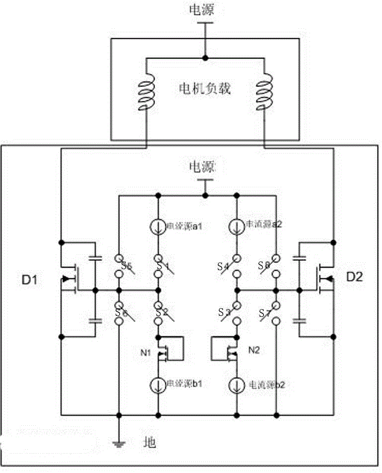
[0011] See figure 2 As shown, a power drive circuit for suppressing current pulses includes a motor load, one end of the motor load is connected to the power supply, the other end is connected to the drain ends of the drive tube D1 and the drive tube D2, and the drain ends of the drive tube D1 and the drive tube D2 are respectively connected to The capacitors are connected to the respective gate terminals, the source terminals of the driving tube D1 and the driving tube D2 are respectively connected to the capacitors and then connected to the respective grid terminals, the source terminals of the driving tube D1 and the driving tube D2 are grounded, and the gate terminals of the driving tube D1 are connected to the switch S5 and the switch S6 One end, the other end of the switch S5 is connected to the power supply, the other end of the switch S6 is grounded, the gate end of the drive tube D2 is connected to the switch S7 and one end of the switch S8, the other end of the switc...


PUM


Abstract

The invention relates to an integrated circuit power drive circuit, in particular into a current pulse restraining power drive circuit; the circuit is simple in structure, the current pulse of the power supply is restrained, and the reliability is improved. The circuit comprises a motor load; one end of the motor load is connected to a power supply, the other end is connected to a drive tube D1 and a drive tube D2, the gate terminal of the drive tube D1 is connected to a switch S5 and a switch S6, and the gate terminal of the drive tube D2 is connected to a switch S7 and a switch S8; the circuit further comprises a first upward pulling current source a1 and a second upward pulling current source a2, one end of the first upward pulling current source a1 is connected to the power supply, the other end is connected to one end of the switch S1, the other end of the switch S1 is connected to the gate terminal of the drive tube D1 and one end of the switch S2, the other end of the switch S2 is connected to the drain and gate terminals of a first NMOS tube N1, the source terminal of the first NMOS tube N1 is connected to one end of a first downward pulling current source b1, the other end of the first downward pulling current source b1 is grounded, and one end of the second upward pulling current source a2 and one end of the first upward pulling current source a1 are connected to a circuit structure and are arranged symmetrically.

Description

technical field [0001] The invention relates to an integrated circuit power drive circuit, in particular to a power drive circuit for suppressing current pulses. Background technique [0002] Small motors have been used more and more in consumer electronic devices. The instantaneous high current pulse will not only cause impact damage to the power system, but may also cause interference and damage to other components in the device. On the other hand, applications require smaller and smaller volumes and lower cost requirements. Therefore, solutions with low cost and satisfactory performance are more and more accepted by people. In order to reduce the size of the motor and the complexity of the design, the current general solution is to provide A monolithically integrated motor drive circuit, such as figure 1 As shown, the drive circuit directly integrates two drive tubes D1, D2 and the drive tube control circuit. In the motor drive system, the complementary drive tube config...

Claims


Application Information

Patent Timeline
Patent Type & Authority Applications(China)
IPC IPC(8): H02P29/00
Inventor 周平
Owner PUYA SEMICON SHANGHAI CO LTD
Features
  • Generate Ideas
  • Intellectual Property
  • Life Sciences
  • Materials
  • Tech Scout
  • Unparalleled Data Quality
  • Higher Quality Content
  • 60% Fewer Hallucinations
Learn More