Intelligent fingerprint password lock

A combination lock and fingerprint technology, applied in the field of all-in-one machines, can solve problems such as insecurity and inconvenient use of locks

Inactive Publication Date: 2015-02-25
CHENGDU LIBANG TECH
View PDF6 Cites 6 Cited by
  • Summary
  • Abstract
  • Description
  • Claims
  • Application Information

AI Technical Summary

Problems solved by technology

[0004] In order to solve the shortcomings of traditional locks such as inconvenient use

Method used


Image

  • Intelligent fingerprint password lock
  • Intelligent fingerprint password lock

Examples


Embodiment 1

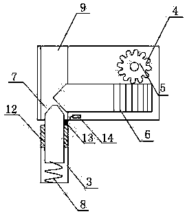
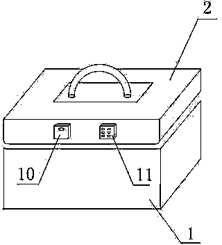
[0016] Such as figure 1 , figure 2 As shown, a kind of intelligent fingerprint combination lock comprises box body 1, box cover 2 that is hingedly connected with box body 1, wherein a side wall of box cover 2 is a cavity structure, and a side wall upper end of box body 1 has cuboid The groove 3 also includes a lock body 4 arranged in the cavity structure, the lock body 4 includes a gear 5 and a gear rod 6 meshed with the gear 5, and the end of the gear rod 6 is a tapered structure; The slide bar 7 on the lower side of the gear bar 6, the upper end of the slide bar 7 is a circular truncated structure; it also includes a housing 9 arranged in the cavity structure, and the slide bar 7 is slidably arranged in the housing 9; the housing 9 There is a hole on the top, and the end of the gear rod 6 passes through the hole to act on the upper end of the slide bar 7; it also includes a fingerprint identification system 10 and a password identification system 11 fixed on the case cover...

Embodiment 2

[0019] In this embodiment, on the basis of Embodiment 1, the upper end of the inner wall of the rectangular parallelepiped groove 3 is provided with a draw-in groove 12, and the slide bar 7 is slidably arranged in the draw-in groove 12; it also includes a spring arranged in the rectangular parallelepiped groove 3 8. One end of the spring 8 is connected to the bottom of the cuboid groove 3, and the other end is connected to the lower end of the slide bar 7.

[0020] In this embodiment, the sliding rod 7 is slidably disposed in the slot 12, which plays a role of limiting the sliding rod 7, so that the sliding rod 7 can only move in the vertical direction. The spring 8 arranged in the cuboid groove 3 gives an upward elastic force to the slide bar 7 when the motor stops moving, so that the slide bar 7 moves upwards, and then the safe is locked.

Embodiment 3

[0022] On the basis of embodiment 1 or embodiment 2, this embodiment also includes a contact point 13 arranged between the cavity structure and the cuboid groove, and also includes an alarm 14 connected to the contact point 13, the alarm 14 set in the cavity structure.

[0023] In this embodiment, when a thief tries to open the safe by picking the lock, once the contact point 13 is touched, the alarm 14 will sound an alarm.


PUM


Abstract

The invention records an intelligent fingerprint password lock. The intelligent fingerprint password lock comprises a box body, and a box cover hinged with the box body, wherein one side wall of the box cover is of a cavity structure; and a cuboid groove is formed in the upper end of one side wall of the box body. The intelligent fingerprint password lock also comprises a lock body arranged in the cavity structure, wherein the lock body comprises a gear and a rack bar meshed with the gear; and the tail end of the rack bar is of a conical structure. The intelligent fingerprint password lock also comprises a sliding rod arranged at the lower side of the rack bar, wherein the upper end of the sliding rod is of a circular truncated cone structure. The intelligent fingerprint password lock also comprises a shell arranged in the cavity structure, wherein the sliding rod is arranged in the shell in a sliding manner; a hole is formed in the shell, and the tail end of the rack bar penetrates through the hole and acts on the upper end of the sliding rod. The intelligent fingerprint password lock also comprises a fingerprint recognition system and a password recognition system which are fixed on the box cover. The intelligent fingerprint password lock has the advantages that due to arrangement of the fingerprint recognition system and the password recognition system, the lock body of a safe box can be unlocked by passwords, and also can be unlocked by fingerprints so as to realize the function of a password and fingerprint integration machine.

Description

[0001] technical field [0002] The invention relates to a safe, in particular to an all-in-one machine capable of unlocking with both passwords and fingerprints. Background technique [0003] In the prior art, the locks basically used in safes are all locksets that utilize simple mechanical structures to operate. To open these mechanical locks, corresponding keys are required, which brings great inconvenience to customers. To open the lock, the customer must be required to carry the key with him, and once the key is lost, it is easy to cause a safety hazard. Once someone picks it up, he can use the picked up key to open the safe, which will bring unnecessary losses to individuals and companies. Contents of the invention [0004] In order to solve the disadvantages of traditional locks such as inconvenient use and unsafety, the present invention provides an intelligent fingerprint combination lock. [0005] Technical scheme of the present invention is as follows: [000...

Claims


Application Information

Patent Timeline
IPC IPC(8): G07C9/00E05B47/00E05B49/00E05G1/10
Inventor 钟坚
Owner CHENGDU LIBANG TECH
Why Eureka
Try Eureka