A redundant power supply circuit for anti-reverse connection and anti-backflow of motor controllers for electric vehicles

A motor controller, electric vehicle technology, applied in the direction of circuit devices, emergency protection circuit devices, electrical components, etc., can solve the problems of reverse connection fault, component burnout, affecting the normal operation of the controller control circuit, etc., to avoid damage , the effect of avoiding damage

Active Publication Date: 2017-12-19
HEFEI JUYI POWER SYST CO LTD
View PDF4 Cites 0 Cited by
  • Summary
  • Abstract
  • Description
  • Claims
  • Application Information

AI Technical Summary

Problems solved by technology

[0002] In the electric vehicle controller, the power required by all chips is converted from DC / DC through the 12V lead-acid battery of the vehicle. If the main power supply stops in an emergency or the main power supply is reversed, It will directly affect the normal operation of the controller control circuit, and then affect the performance of the vehicle, resulting in hidden dangers to driving safety.
For the first case, there is no dual power supply method yet; for the anti-reverse connection of the main power supply, the existing anti-reverse connection technology uses diodes for reverse connection protection. The problem with this technology is the conduction voltage drop of the diodes. If it is too large, when the input current is high, the power consumption will be large, the efficiency will be reduced, and the heat will be large, which may cause the components to burn out
So far there is no public report on the redundant power supply method of anti-reverse connection and anti-backflow of electric vehicle motor controller

Method used


Image

  • A redundant power supply circuit for anti-reverse connection and anti-backflow of motor controllers for electric vehicles

Examples


Embodiment Construction

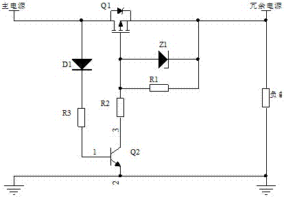
[0009] A redundant power supply circuit for anti-reverse connection and anti-backflow of a motor controller for an electric vehicle, comprising a MOS transistor Q1, the drain of which is connected to the anode of a diode D1 and then connected to the main power supply, the cathode of the diode D1 is connected to one end of a resistor R3, and the resistor The other end of R3 is connected to the base of the transistor Q2, the emitter of the transistor Q2 is grounded, the collector of the transistor Q2 is connected to the gate of the MOS transistor Q1 through the resistor R2, and the source of the MOS transistor Q1 is respectively connected to the redundant power supply and the load. Connected at one end, the other end of the load is grounded, such as figure 1 As shown, the base of the triode Q2 is pin 1, the emitter of the triode Q2 is pin 2, and the collector of the triode Q2 is pin 3.

[0010] Such as figure 1 As shown, the present invention also includes a Zener diode Z1, who...


PUM


Abstract

The invention relates to a redundant power supply circuit for anti-reverse connection and anti-backflow of a motor controller for an electric vehicle, comprising a MOS transistor Q1, the drain of which is connected to the anode of a diode D1 and then connected to the main power supply, and the cathode of the diode D1 is connected to one end of a resistor R3 The other end of the resistor R3 is connected to the base of the transistor Q2, the emitter of the transistor Q2 is grounded, the collector of the transistor Q2 is connected to the gate of the MOS transistor Q1 through the resistor R2, and the source of the MOS transistor Q1 is respectively connected to the redundant power supply , One end of the load is connected, and the other end of the load is grounded. The present invention can monitor the power supply situation of the main power supply in real time. When the main power supply is reversely connected, the MOS tube Q1 shuts off the output to prevent related devices from still working in the state of power supply failure and avoid damage to the devices, especially the power device IGBT; when the main power supply is disconnected When the power is turned on, the redundant power supply starts to work. At this time, the MOS tube Q1 is disconnected, cutting off the circuit between the redundant power supply and the main power supply, and preventing the redundant power supply from being poured into the main power supply.

Description

technical field [0001] The invention relates to the technical field of electric vehicles, in particular to a redundant power supply circuit for anti-reverse connection and anti-backflow of a motor controller for an electric vehicle. Background technique [0002] In the electric vehicle controller, the power required by all chips is converted from DC / DC through the 12V lead-acid battery of the vehicle. If the main power supply stops in an emergency or the main power supply is reversed, It will directly affect the normal operation of the controller control circuit, and then affect the performance of the vehicle, resulting in hidden dangers to driving safety. For the first case, there is no dual power supply method yet; for the anti-reverse connection of the main power supply, the existing anti-reverse connection technology uses diodes for reverse connection protection. The problem with this technology is the conduction voltage drop of the diodes. If it is too large, when a la...

Claims


Application Information

Patent Timeline
Patent Type & Authority Patents(China)
IPC IPC(8): H02H11/00H02J9/04
Inventor 林巨广尹亚琴孙纯哲徐义苑红伟
Owner HEFEI JUYI POWER SYST CO LTD
Why Eureka
Try Eureka