
Drill rod automatic treatment device

A technology for automatic handling and drilling of drill pipes, applied in the direction of drill pipes, drill pipes, drilling equipment, etc.

Inactive Publication Date: 2015-03-04
邹家福 +2
View PDF1 Cites 4 Cited by
  • Summary
  • Abstract
  • Description
  • Claims
  • Application Information

AI Technical Summary

Problems solved by technology

[0004] The shortcoming of above-mentioned drilling rod automatic stacking conveying device is: 1, must arrange main slideway and front slideway
2. Cars must be set on the main slideway
3. The trolley must be equipped with a locking device on the main slideway and the front slideway
4. When the trolley walks on the main slideway, a driving device must be added

Method used


Image

  • Drill rod automatic treatment device
  • Drill rod automatic treatment device
  • Drill rod automatic treatment device

Examples


Embodiment Construction

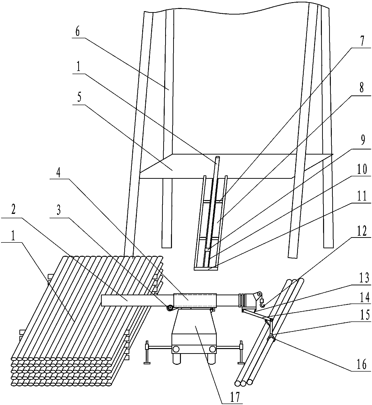
[0012] figure 1 A slideway 10 is arranged in the middle of the ramp 8 in front of the Zhongjing platform 5, and the upper and lower sides of the slideway 10 are symmetrically arranged with a pipe row block 7. The outer ends of the pipe row block 7 can be raised and inclined to the slideway. Clamp nearby drill pipe.

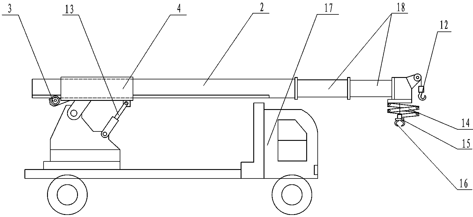
[0013] figure 2 Middle is the horizontal zoom-in view of the automatic drill pipe handling vehicle. A boom base 4 is arranged at the rear of the main boom 2 of a general truck crane. There is a splint on the bottom left side of the boom base 4 to be hinged with the upper part of the truck crane turntable, and the right side is connected with the car turntable by a hydraulic cylinder (comprising a piston rod) 13. The lower left end of the boom seat 4 is provided with a main boom driving device 3, which has two modes of gear drive and wire rope drive. What draw among the figure is gear drive, and what drive with gear just is provided with rack at one side below...


PUM


Abstract

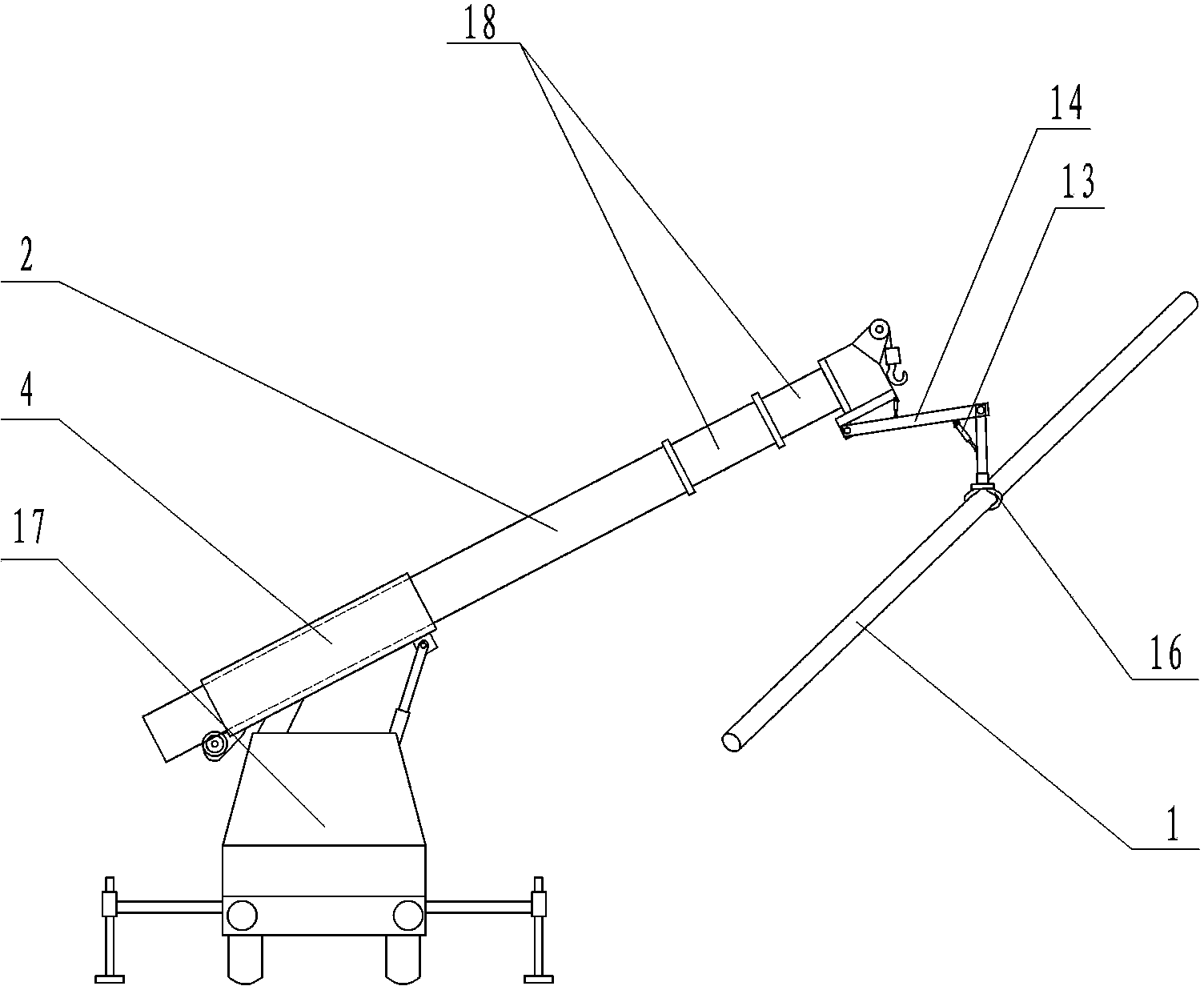
A drill rod automatic treatment device is a device for automatically stacking drill rods on a petroleum and natural gas well site and automatically conveying the drill rods to a wellbay. The device is composed of a ramp portion and a drill rod automatic treatment vehicle. A suspension arm base is arranged on the rear portion of a main suspension arm of an automobile telescopic arm crane, and the main suspension arm is arranged in the suspension arm base to be capable of moving front and back; and a clamping arm and clamping jaw mechanism for grabbing and clamping the drill rods or steel pipes is arranged below the end of a telescopic arm at the last section. According to the drill rod grabbing distance, the main suspension arm moves backwards and forwards, and the telescopic arm is correspondingly shortened and extended. A sliding way, a trolley and tube bank blocks are arranged on the ramp. The automatic treatment vehicle clamps the drill rods and puts the drill rods on the tube bank blocks of the ramp, and after entering the sliding way, the drill rods are automatically conveyed to the wellbay. The device is controlled by a computer program, so that the aims that unmanned operation is achieved, and one person can also operate the device are achieved. The heavy manual labor of a worker is reduced, and the working efficiency is improved; and objects in the well site can be lifted, so that one machine has multiple functions. The vehicle can be driven into the site to be used when the well site is moved, and work in the aspects of disassembling, conveying and mounting is reduced.

Description

technical field [0001] The invention belongs to oil drilling equipment, in particular to an automatic processing device for drill pipes. Background technique [0002] In existing oil and gas land drilling, there are few automatic drill pipe handling devices on the well site. On the land drilling well site, the drill pipe or steel pipe (hereinafter referred to as the drill pipe) is sent from the ground to the well platform. The poles are hoisted to the well platform, and the workers have to go to work day and night to repeat heavy physical labor no matter it is windy or rainy, hot or cold. [0003] Drill pipe automatic stacking and conveying device, patent number 201220091964.8, can automatically stack drill pipes on the well site, and can automatically clamp the drill pipes and put them in the slide on the ramp. The trolley on the slide can push the drill pipes to the well platform. The automation of stacking and conveying of drill pipes on the well site is realized, whic...

Claims


Application Information

Patent Timeline
IPC IPC(8): E21B19/14
CPCE21B19/14
Inventor 邹家福邹永平邹家鸿邹家华胡冬梅
Owner 邹家福
Learn More