An angular precision positioning centering clamping mechanism

A technology of precise positioning and clamping mechanism, which is applied in the direction of positioning devices, clamping, metal processing machinery parts, etc. It can solve the problems of machining error angular positioning accuracy, positioning axis deflection, and low precision requirements, etc., to achieve guaranteed position Consistent, high positioning and centering accuracy, and the effect of meeting the requirements of machining accuracy

Inactive Publication Date: 2016-09-07
SHENYANG LIMING AERO-ENGINE GROUP CORPORATION
View PDF5 Cites 0 Cited by
  • Summary
  • Abstract
  • Description
  • Claims
  • Application Information

AI Technical Summary

Problems solved by technology

[0005] ①The circular sleeve is used for positioning, affected by the processing tolerance of the blade and the circular sleeve, there is a certain positioning gap when the two are reassembled. When the angular positioning block is pressed, the positioning axis will be deflected
[0006] ②When the angular positioning block slides in the square mouth of the circular sleeve, there will be a certain sliding gap. Since the positioning surface is small, this has a great influence on the angular positioning, and the machining error of the angular positioning block will also affect the angular positioning. Accuracy affects
[0007] ③ After the blade journal is tightened, the angular direction of the blade can no longer be adjusted, and once the angular direction is fixed, the fixed angle will change again when the journal is tightened, so it is difficult to ensure that the blade Angular positioning requirements for
[0008] Therefore, the above method can only meet the blades with low precision requirements, and for the blades with high precision requirements, this traditional positioning method can no longer meet the precision requirements of the blades.

Method used


Image

  • An angular precision positioning centering clamping mechanism
  • An angular precision positioning centering clamping mechanism
  • An angular precision positioning centering clamping mechanism

Examples


Embodiment Construction

[0025] The present invention will be further described in detail below in conjunction with the accompanying drawings and specific embodiments.

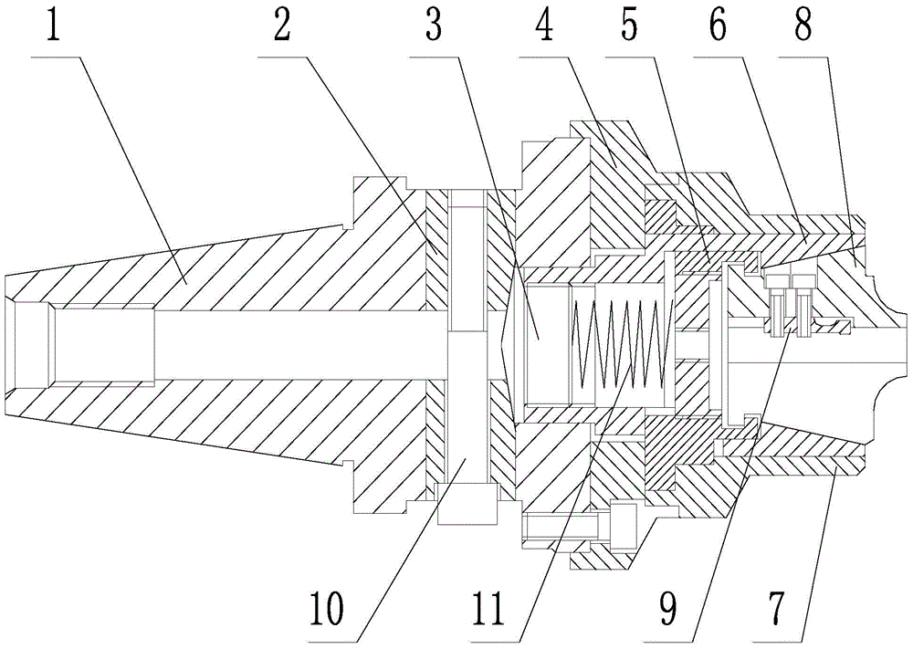
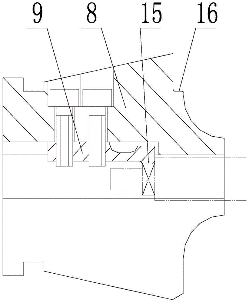
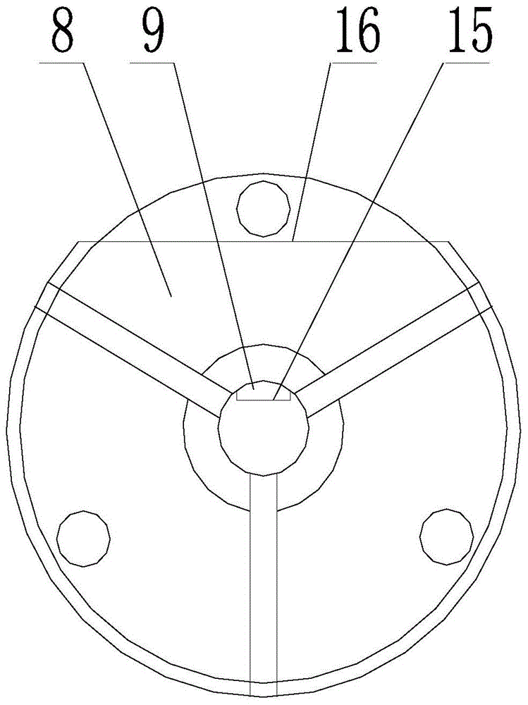
[0026] Such as figure 1 , 2 , 3, a kind of angular precision positioning centering clamping mechanism, including taper handle 1, wedge 2, cone 3, base 4, card seat 5, taper sleeve 6, outer jacket 7 and chuck 8, in There is a through groove in the radial direction on the taper shank 1, and a round hole is opened in the center of the taper shank 1 in the axial direction. The wedge 2 is located in the through groove of the taper shank 1. There are two wedges 2, two The two wedges 2 are arranged opposite to each other, and the two wedges 2 are connected together by clamping bolts 10; touch;

[0027] The inner end of the taper sleeve 6 is fixedly connected with the back side of the cone body 3, the cone body 3 is slidingly matched with the round hole of the taper handle 1, the outer sleeve 7 is set on the outer end of the taper sleeve 6...


PUM


Abstract

The invention discloses an angular precise positioning and centering clamping mechanism, and belongs to the technical field of aero-engine part manufacturing. A wedge block of the angular precise positioning and centering clamping mechanism disclosed by the invention is located in a through slot of a taper shank, and is driven by a clamping bolt; a taper and the wedge block are matched in a contact manner; the inner end of a taper sleeve is fixedly connected with the back side of the taper; an outer cover covers the outer end of the taper sleeve; the outer cover is fixedly connected with the taper shank through a substrate; a chuck is connected with a clamping seat; the taper sleeve is matched with the chuck; the chuck is of a multi-section structure as a whole, and each two sections are connected by elastic rubber; the inner surface of the chuck is provided with an elastic positioning block; the elastic positioning block is matched with a blade flat; the matching range between the diameter of the inner surface of the chuck and the dimension of a large blade journal is plus or minus 0.2mm. According to the angular precise positioning and centering clamping mechanism disclosed by the invention, the blade flat is compressed by the elastic positioning block to realize angular positioning; the blade journal is enclasped by the chuck to realize gapless centering and positioning; the annular positioning on the blade flat cannot interfered with the operation that the blade journal is enclasped by the chuck, and simultaneous positioning of the journal and the flat is realized; the positioning and centering precision is high, and the machining precision requirement of a blade can be met.

Description

technical field [0001] The invention belongs to the technical field of aero-engine parts manufacturing, in particular to an angular precision positioning centering clamping mechanism. Background technique [0002] As the core component of an aero-engine, the blade requires high machining accuracy, but due to the limitation of the blade's own structure, its processing and positioning are difficult. Taking an adjustable-angle blade as an example, when processing this type of blade, the blade profile is required The angle and the square flat at the end of the large journal have relatively high relative accuracy. When machining the blade body, the angle is determined by the square flat, and the center is centered by the journal. [0003] At present, the traditional blade centering positioning and clamping method is adopted. The center of the journal is ensured through the positioning of the circular sleeve. The square flat is located inside the circular sleeve. Angular position...

Claims


Application Information

Patent Timeline
Patent Type & Authority Patents(China)
IPC IPC(8): B23Q3/12
CPCB23Q3/12
Inventor 彭会文张娟赵西松金秀杰申玉萍
Owner SHENYANG LIMING AERO-ENGINE GROUP CORPORATION
Why Eureka
Try Eureka