
Servo autotracking support for bent axle grinding

An automatic tracking and support device technology, which is applied in the direction of grinding workpiece supports, machine tools designed for grinding workpiece rotating surfaces, grinding/polishing equipment, etc., can solve the influence of support rigidity and working stability pulsation, and is not suitable for fixing Adjustable center frame, expensive imports and other issues, to achieve the effect of improving the overall grade and value, high centering accuracy, and improving accuracy and stability

Inactive Publication Date: 2008-02-06
HUNAN HICAM PRECISION IND
View PDF0 Cites 6 Cited by
  • Summary
  • Abstract
  • Description
  • Claims
  • Application Information

AI Technical Summary

Problems solved by technology

[0002] The crankshaft is composed of the main journal and the eccentric connecting rod journal alternately. It is a typical spring-type part, and the grinding rigidity is poor. Due to the eccentric structure of the crankshaft, it is not suitable to use a fixed and adjustable steady rest, especially for the grinding of the connecting rod neck. Adopt automatic tracking type support device with tool rest
On the traditional crankshaft grinding machine, the main journal is generally divided into two processes. First, the intermediate journal is processed, and then it is positioned. The fixed and adjustable center frame is used to grind other journals. The connecting rod journal generally does not use the intermediate support. The grinding accuracy is low and the efficiency is very slow, which cannot meet the development requirements of the automobile industry. Imported machine tools generally use two support devices, hydraulic automatic tracking and electronic tracking, to solve this problem, but the import price is expensive, and a domestically designed one can be used for crankshafts. Grinding hydraulic automatic tracking steady frame, but its support rigidity and working stability are affected by temperature and hydraulic pulsation, and adjustment is difficult

Method used


Image

  • Servo autotracking support for bent axle grinding

Examples


Embodiment Construction

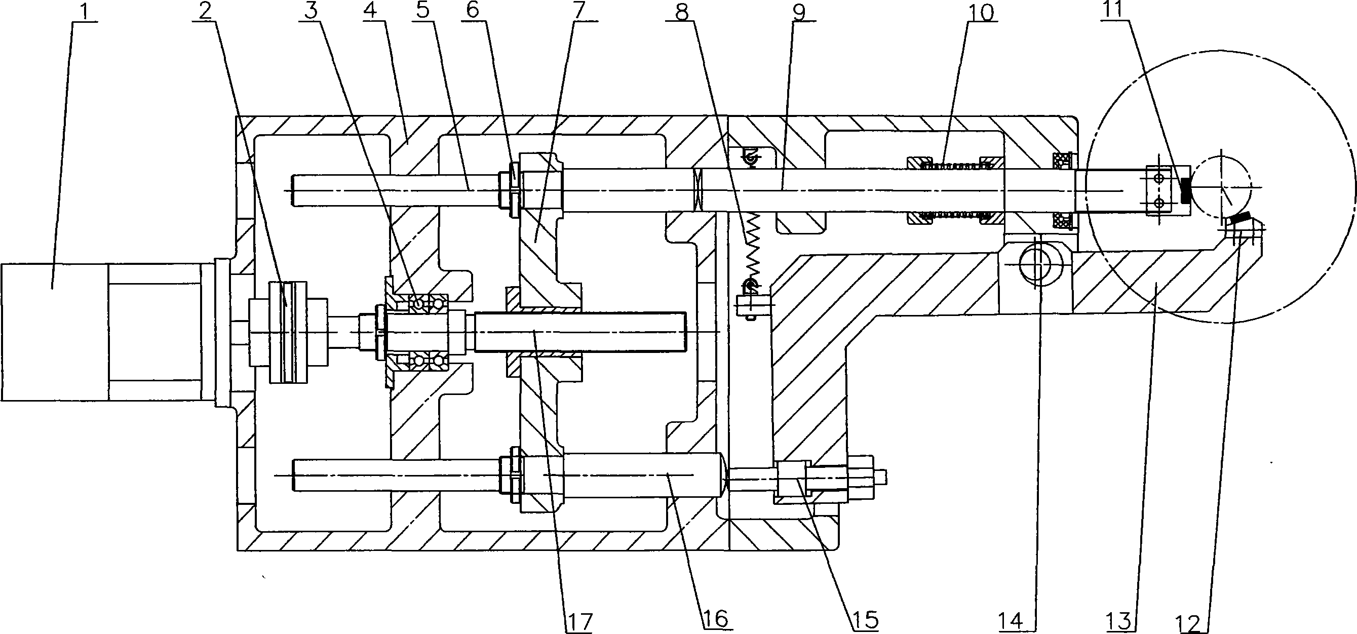
[0019] Referring to the accompanying drawings, a ball screw 17 is installed on the box body 4 through a screw bearing 3, and a servo motor 1 is installed on the box body 4, and the servo motor 1 is connected with the ball screw 17 through a coupling 2 without clearance. The ball screw 17 is set with the drive link 7, and the upper drive rod 5 and the lower drive rod 16 are slidably installed on the box body 4, and the upper drive rod 5 and the lower drive rod 16 are fixedly connected with the drive link 7 through the lock nut 6 , the upper support arm 9 with the first return spring 10 is slidably installed on the box body 4, one end of the upper support arm 9 is correspondingly driven with the upper drive rod 5, and the other end is provided with an upper support alloy 11, which passes on the box body 4 The adjustable eccentric shaft 14 is equipped with a lower support arm 13 with a second return spring 8, one end of the lower support arm 13 is provided with an adjustable push ...


PUM


Abstract

The invention discloses a servo automatic tracing support device for crank shaft grinding process, a box body (4) is provided with a ball-bearing thread bar (17) and a servo motor (1), the ball-bearing thread bar (17) is provided with a driving connection rod (7), an upper driving rod (5) and a lower driving rod (16) fixed with the driving connection rod (7) are slidingly arranged on the box body (4), an upper support arm (9) with a first reset spring (10) is slidingly arranged on the box body (4), one end of the upper support arm (9) is driven with the upper driving rod (5) correspondingly while the other end is provided with an upper support alloy (11), the box body (4) also is pin-jointed with a lower support arm (13) with a second reset spring (8), one end of the lower support arm (13) is driven with the lower driving rod (16) correspondingly while the other end is provided with a lower support alloy (12), and the upper support alloy (11) and the lower support alloy (12) are distributed from 100 DEG C to 120 DEG C; the invention can conduct the automatic tracing and centering grinding process where the crank shaft grinding process is synchronized with the sand wheel feeding process, and effectively improve the accuracy and stability of crank shaft grinding process, and improves the automatic control degree of the machine tool, and increase the overall taste and value of the machine tool.

Description

technical field [0001] The invention relates to a support device, in particular to a servo automatic tracking support device for crankshaft grinding. Background technique [0002] The crankshaft is composed of the main journal and the eccentric connecting rod journal alternately. It is a typical spring-type part, and the grinding rigidity is poor. Due to the eccentric structure of the crankshaft, it is not suitable to use a fixed and adjustable steady rest, especially for the grinding of the connecting rod neck. It adopts the automatic tracking tool rest support device. On the traditional crankshaft grinding machine, the main journal is generally divided into two processes. First, the intermediate journal is processed, and then positioned. The fixed and adjustable center frame is used to grind the other journals. The connecting rod journal generally does not use the intermediate support. The grinding accuracy is low and the efficiency is very slow, which cannot meet the dev...

Claims


Application Information

Patent Timeline
Patent Type & Authority Applications(China)
IPC IPC(8): B24B5/42B24B41/06
Inventor 彭克立张才友陶剑波黄险峰
Owner HUNAN HICAM PRECISION IND
Learn More