Vehicle engine suspension structure
A technology for vehicle engines and mounts, which is applied to power plants, vehicle parts, jet propulsion devices, etc., can solve problems such as difficult adjustment, large displacement, and poor decoupling effect of the mount system, achieving space reduction, The effect of reasonable stiffness
- Summary
- Abstract
- Description
- Claims
- Application Information
AI Technical Summary
Problems solved by technology
Method used
Image
Examples
Embodiment Construction
[0016] The specific embodiment of the present invention will be described in further detail by describing the embodiments below with reference to the accompanying drawings, the purpose is to help those skilled in the art to have a more complete, accurate and in-depth understanding of the concept and technical solutions of the present invention, and contribute to its implementation.
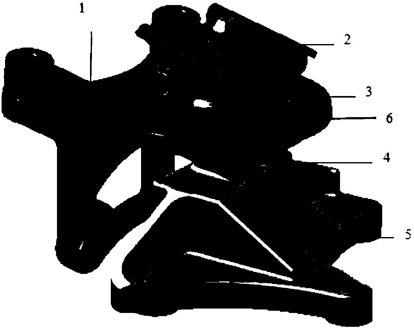
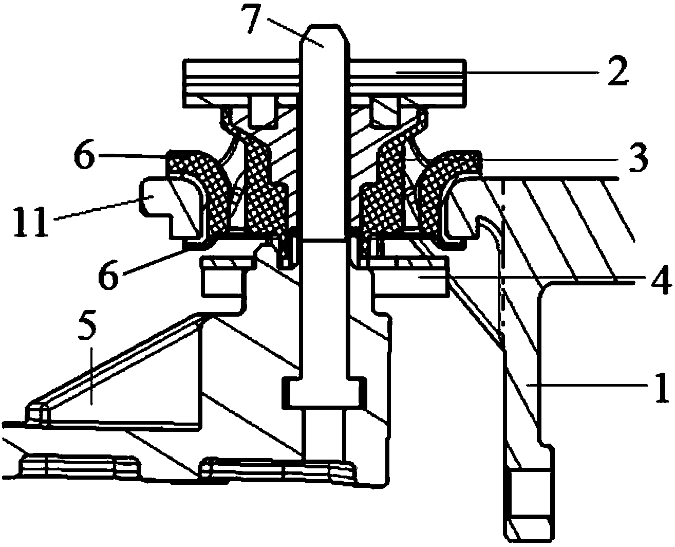
[0017] like figure 1 and figure 2 As shown, the present invention provides a vehicle engine suspension structure, comprising a suspension bracket 5, a suspension frame body 1, a support nail 7 arranged on the suspension bracket 5 and a ferrule arranged on the suspension frame body 1 11 and let the supporting nail 7 pass through the rubber main spring 3, the rubber main spring 3 is located above the suspension bracket 5, and the rubber main spring 3 adopts the structure of four tendons. The suspension frame body 1 is used to connect with the engine, the ferrule 11 of the suspension frame body 1 ...
PUM
 Abstract
Description
Claims
Application Information
 - R&D
- Intellectual Property
- Life Sciences
- Materials
- Tech Scout
- Unparalleled Data Quality
- Higher Quality Content
- 60% Fewer Hallucinations
Browse by: Latest US Patents, China's latest patents, Technical Efficacy Thesaurus, Application Domain, Technology Topic, Popular Technical Reports.
© 2025 PatSnap. All rights reserved.Legal|Privacy policy|Modern Slavery Act Transparency Statement|Sitemap|About US| Contact US: help@patsnap.com


