3D display backlight module and control method, 3D display device

A backlight module and control method technology, applied in optics, optical components, nonlinear optics, etc., can solve the problems of whitening in the middle area, long transmission distance of super-sized panels, and huge data volume, etc., to improve picture quality, Lightening effect, lightening effect

Active Publication Date: 2017-01-04
BOE TECH GRP CO LTD +1
View PDF8 Cites 0 Cited by
  • Summary
  • Abstract
  • Description
  • Claims
  • Application Information

AI Technical Summary

Problems solved by technology

[0002] In the field of display, ultra-high-resolution and ultra-large-size flat-panel displays are the focus of competition. However, with the continuous improvement of resolution and the growing market demand for 3D display, the amount of data that panel drive circuits need to transmit and process At the same time, the transmission distance on the ultra-large panel is very long, so it is facing severe signal integrity problems
[0003] Based on the above problems, at present, for ultra-large-size and ultra-high-resolution display panels, such as 3D display panels with a resolution of 3840×2160 and a refresh rate of 120Hz, a display principle based on splicing has appeared. However, due to the principle of splicing display, the panel Sometimes the scanning direction of the backlight module needs to be changed to the way of facing up and down or away from up and down, and the scanning direction of the backlight module must also correspond to the scanning direction of the display panel during 3D display. figure 1 It is the partition structure of the backlight module in the prior art. During 3D display, two partitions are turned on in the middle area of ​​the backlight module at the same time, and the brightness is larger than that of other areas, so the phenomenon of whitening in the middle area occurs, which seriously affects picture quality

Method used


Image

  • 3D display backlight module and control method, 3D display device
  • 3D display backlight module and control method, 3D display device
  • 3D display backlight module and control method, 3D display device

Examples


Embodiment Construction

[0027] In order to make the object, technical solution and advantages of the present invention clearer, the present invention will be described in detail below with reference to the accompanying drawings and specific embodiments.

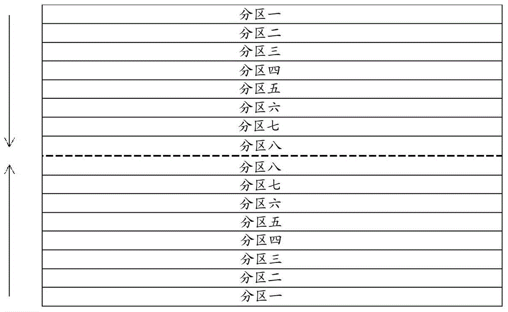
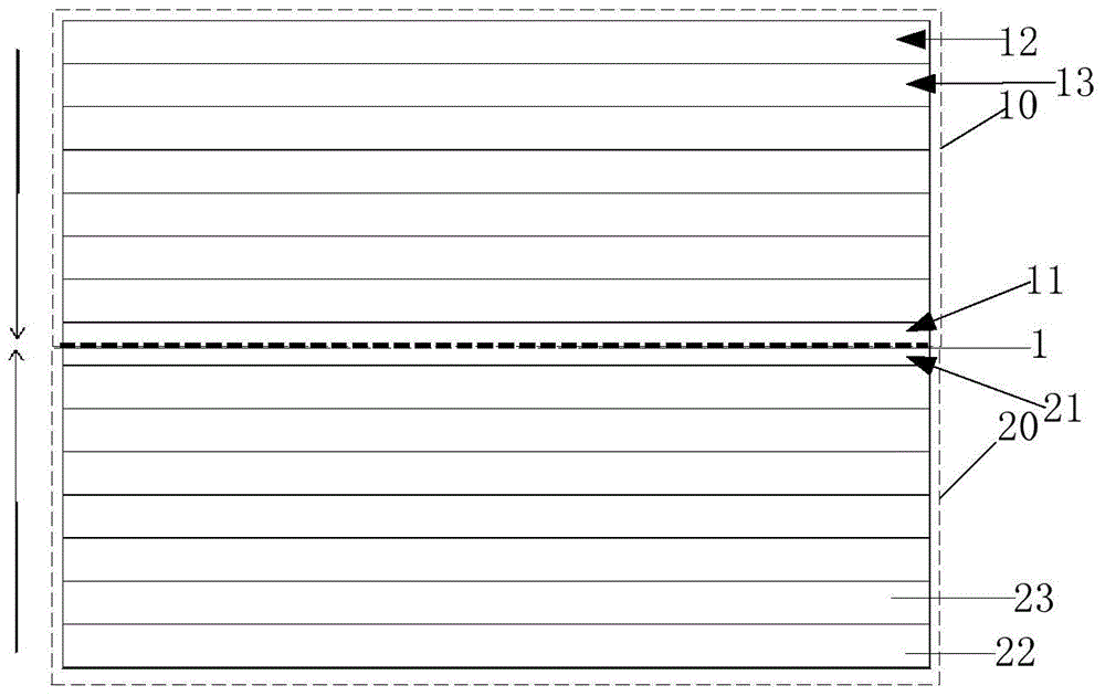
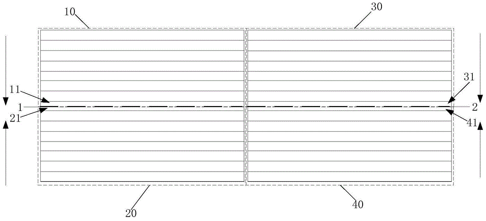
[0028] The 3D display backlight module according to the specific embodiment of the present invention includes at least one backlight area, wherein the backlight area includes at least two first sub-backlight areas and second sub-backlight areas arranged in sequence, and the first sub-backlight area The second sub-backlight area includes at least two sub-backlight units respectively, and the arrangement direction of each sub-backlight unit is the same, and the first sub-backlight unit in the first sub-backlight area and the first corresponding sub-backlight unit in the second sub-backlight area The units have a common adjoining side, and the extension direction of the common adjoining side is the length direction of the sub-backlight unit, wherein the...


PUM


Abstract

The invention provides a 3D display backlight module, a control method thereof and a 3D display. The 3D display backlight module comprises at least one backlight region, wherein the backlight region comprises a first subsidiary backlight region and a second subsidiary backlight region which are sequentially arranged, the first subsidiary backlight region and the second subsidiary backlight region respectively comprise at least two subsidiary backlight units, the first subsidiary backlight unit in the first subsidiary backlight region and the first corresponding subsidiary backlight unit in the second subsidiary backlight region share a common boundary edge, the extension direction of the common boundary edge is the length direction of the subsidiary backlight units, and the sum of the width of the first subsidiary backlight unit and the width of the first corresponding subsidiary backlight unit is smaller than or equal to the width of any other subsidiary backlight unit in the first subsidiary backlight region and the second subsidiary backlight region. The backlight module can be applied to an oversized 3D display. The brightening degree of a middle region produced during 3D display is reduced, so that the picture quality of 3D display is improved.

Description

technical field [0001] The invention relates to the technical field of liquid crystal display, in particular to a 3D display backlight module, a control method, and a 3D display device. Background technique [0002] In the field of display, ultra-high-resolution and ultra-large-size flat-panel displays are the focus of competition. However, with the continuous improvement of resolution and the growing market demand for 3D display, the amount of data that panel drive circuits need to transmit and process At the same time, the transmission distance on the super-sized panel is very long, so it is facing severe signal integrity problems. [0003] Based on the above problems, at present, for ultra-large-size and ultra-high-resolution display panels, such as 3D display panels with a resolution of 3840×2160 and a refresh rate of 120Hz, a display principle based on splicing has appeared. However, due to the principle of splicing display, the panel Sometimes the scanning direction o...

Claims


Application Information

Patent Timeline
Patent Type & Authority Patents(China)
IPC IPC(8): G09G3/34G02B27/22G02F1/13357
Inventor 何宗泽尹大根胡巍浩王健铭于杨冰
Owner BOE TECH GRP CO LTD
Why Eureka
Try Eureka