Undulator

An undulator and fundamental wave technology, applied in the field of synchrotron radiation, can solve the problems of inability to effectively remove heat load and weak auxiliary magnetic field, and achieve the effects of simple installation, reduction of heat load and cost saving

Active Publication Date: 2015-03-11
SHANGHAI INST OF MICROSYSTEM & INFORMATION TECH CHINESE ACAD OF SCI
View PDF7 Cites 8 Cited by
  • Summary
  • Abstract
  • Description
  • Claims
  • Application Information

AI Technical Summary

Problems solved by technology

[0005] In view of the above-mentioned shortcomings of the prior art, the purpose of the present invention is to provide an undulator, which is used to solve the high heat load when the existing undulator technology produces synchrotron radiation, and the auxiliary energy generated by the four rows of magnets outside the APPLE-Knot undulator. The magnetic field is weak and cannot effectively remove the problem of heat load

Method used


Image

  • Undulator
  • Undulator
  • Undulator

Examples


Embodiment Construction

[0047] Embodiments of the present invention are described below through specific examples, and those skilled in the art can easily understand other advantages and effects of the present invention from the content disclosed in this specification. The present invention can also be implemented or applied through other different specific implementation modes, and various modifications or changes can be made to the details in this specification based on different viewpoints and applications without departing from the spirit of the present invention.

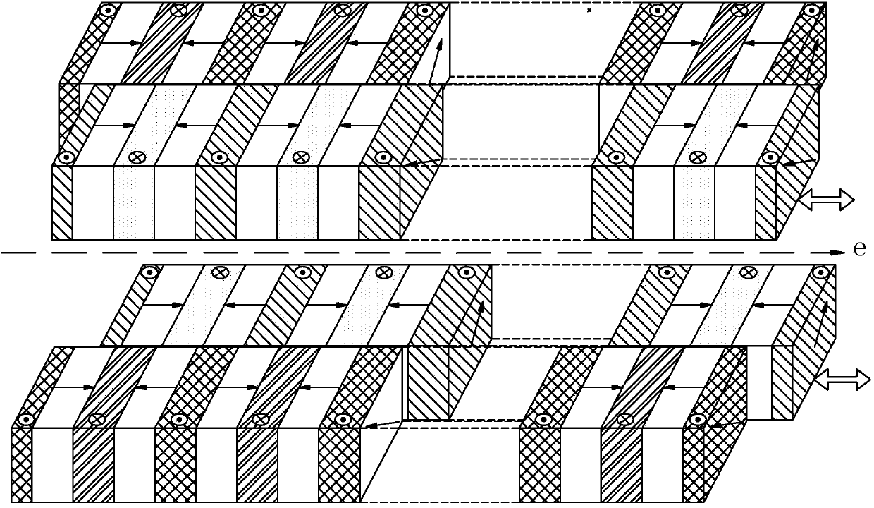
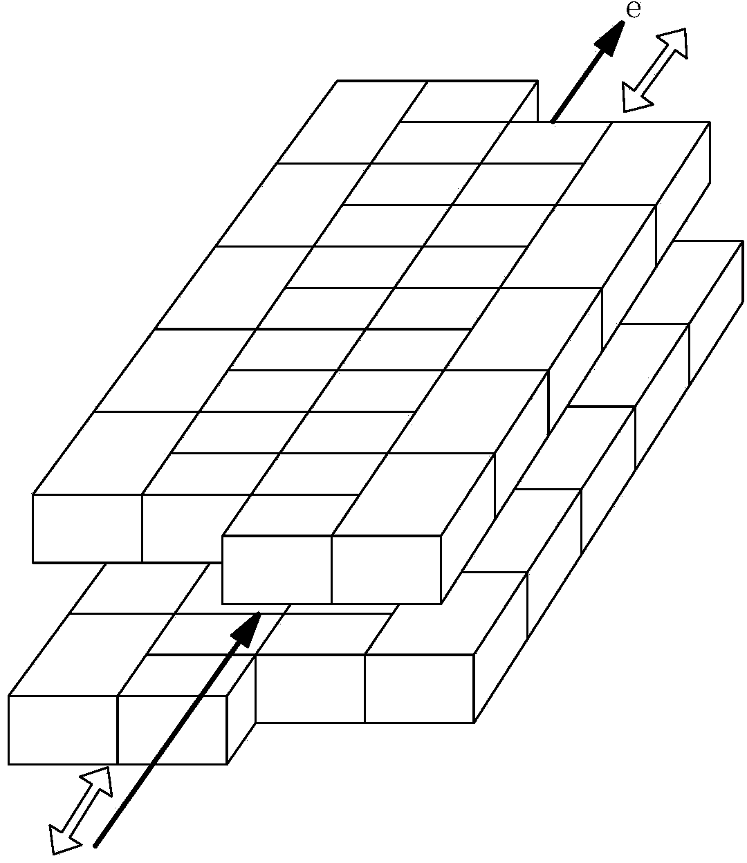
[0048] The undulator of the present invention at least includes: M permanent magnet periods arranged in sequence along the electron beam transmission direction, each permanent magnet period includes four rows of permanent magnet structures, each row of permanent magnet structures includes N rows of permanent magnet groups, and each row of permanent magnets The group includes K permanent magnet units, wherein M, N, and K are all natural...


PUM

PropertyMeasurementUnit
magnetic fieldaaaaaaaaaa
lengthaaaaaaaaaa

Abstract

The invention provides an undulator. The undulator at least comprises M permanent magnet cycles which are sequentially arranged along the direction to which an electron beam transmits; each permanent magnet cycle is composed of four rows of permanent magnet structures, each row comprising N rows of permanent magnet sets, wherein each row of permanent magnet sets comprises K permanent magnet units; M, N and K are all the natural numbers more than and equal to 1; the permanent magnet structures in the four rows are pairwise coupled and then are oppositely arranged at two sides in the along to which the electron beam transmits and relatively displace to form at least one combined magnetic field through which the electron beam emits elliptically polarized light, circularly polarized light or linearly polarized light in any polarizing angle of 0 to 360 degrees, and the electron velocity direction is deviated from the direction of an axis of the undulator. The undulator has the advantages that either linearly polarized light or elliptically and circularly polarized lights can be produced, and the electron velocity direction is deviated from the direction of the axis of the undulator all the times, so that the thermal load of the synchronously-radiated beam lines can be greatly reduced.

Description

technical field [0001] The invention relates to the technical field of synchrotron radiation, in particular to an undulator. Background technique [0002] The full name of synchrotron radiation is synchrotron radiation, which is a high-intensity, highly collimated beam emitted by high-energy electrons when they are deflected in a magnetic field. In order to produce synchrotron radiation with higher intensity, current synchrotron radiation facilities use a large number of undulators. The undulator generates a periodically changing magnetic field, and the high-energy electron beam moves periodically in the undulator, and the generated light has higher intensity due to the interference effect. With the development of accelerator technology, the divergence of electron beams becomes smaller and smaller, and the heat load (the sum of the power of all energy photons) on optical components (such as mirrors, gratings, and crystals) becomes larger and larger. On the other hand, with...

Claims


Application Information

Patent Timeline
Patent Type & Authority Applications(China)
IPC IPC(8): G21K1/00H01F7/02
CPCG21K1/003H01F7/0278H05H7/04H05H2007/041H01F7/02H05H13/04
Inventor 乔山常睿季福昊叶茂
Owner SHANGHAI INST OF MICROSYSTEM & INFORMATION TECH CHINESE ACAD OF SCI
Why Eureka
Try Eureka