
3D panel, driving method of 3D panel and electronic equipment

一种驱动方法、3D的技术,应用在3D显示领域,能够解决画面切换残影、充电极性不能发生翻转等问题,达到消除残影的效果

Active Publication Date: 2015-03-11
SHANGHAI TIANMA MICRO ELECTRONICS CO LTD +1
View PDF5 Cites 8 Cited by
  • Summary
  • Abstract
  • Description
  • Claims
  • Application Information

AI Technical Summary

Problems solved by technology

[0003] When the existing technology drives a 3D panel for 3D image display, the charging polarity of each pixel unit of two adjacent 3D images cannot be reversed, resulting in image sticking when switching screens

Method used


Image

  • 3D panel, driving method of 3D panel and electronic equipment
  • 3D panel, driving method of 3D panel and electronic equipment
  • 3D panel, driving method of 3D panel and electronic equipment

Examples


Embodiment Construction

[0031] The following will clearly and completely describe the technical solutions in the embodiments of the present invention with reference to the accompanying drawings in the embodiments of the present invention. Obviously, the described embodiments are only some, not all, embodiments of the present invention. Based on the embodiments of the present invention, all other embodiments obtained by persons of ordinary skill in the art without making creative efforts belong to the protection scope of the present invention.

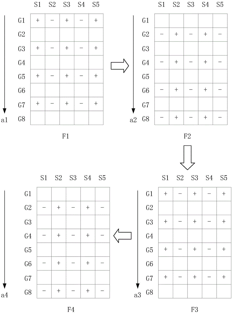
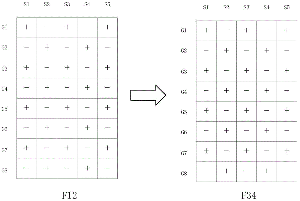
[0032] When the existing driving method drives the 3D panel to display the 3D picture, refer to figure 1 and figure 2 , figure 1 It is a schematic diagram of the charging polarity of the 3D panel in one cycle of the existing driving method, figure 2 for figure 1 Schematic diagram of the 3D display of the driving method shown. figure 1 The illustrated embodiment takes a 3D panel with 8×5 pixel units as an example, and the 3D panel includes: 8×5 pixel unit...


PUM


Abstract

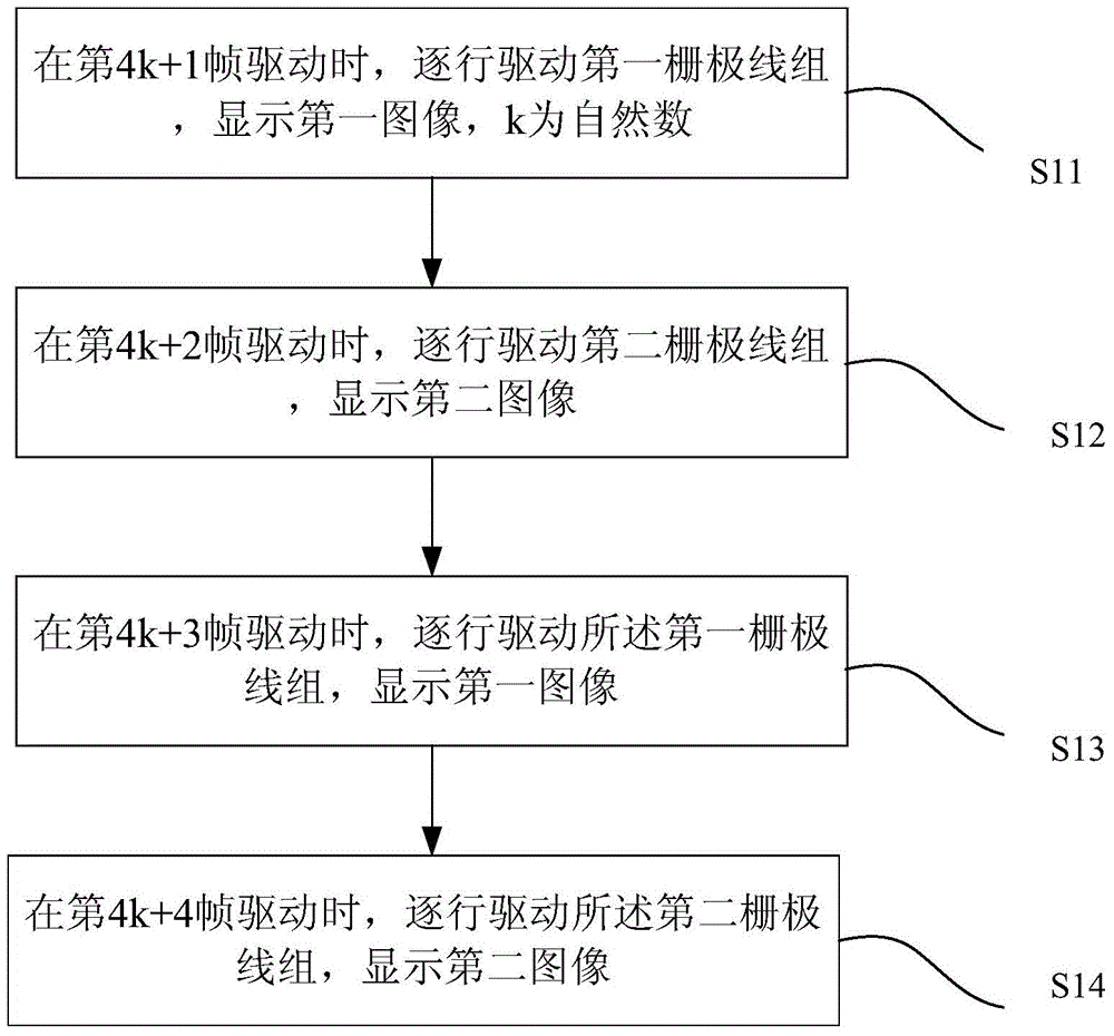
The invention discloses a 3D panel, a driving method of the 3D panel and electronic equipment. The driving method comprises steps as follows: during driving of a (4k+1) frame, a first grid line group is driven line by line, a first image is displayed, and k is a natural number; during driving of a (4k+2) frame, a second grid line group is driven line by line, and a second image is displayed; during driving of a (4k+3) frame, the first grid line group is driven line by line, and the first image is displayed; during driving of a (4k+4) frame, the second grid line group is driven line by line, and the second image is displayed; one of the first image and the second image is a left eye image, and the other is a right eye image; grid lines of the first grid line group and grid lines of the second grid line group are arranged alternately; scanning directions of the (4k+1) frame and the (4k+3) frame are opposite; and scanning directions of the (4k+2) frame and the (4k+4) frame are opposite. With the adoption of the driving method, charge polarities of pixel units of every two adjacent 3D images are turned, and the problem of ghost images is solved.

Description

technical field [0001] The present invention relates to the technical field of 3D display, and more specifically, relates to a 3D panel, a driving method thereof, and an electronic device. Background technique [0002] The 3D panel divides the ordinary pixel unit into two, and divides it into a left-eye pixel unit and a right-eye pixel unit. When displaying a 2D image, the left-eye pixel unit and the right-eye pixel unit display the same information, and when displaying a 3D image, display a left-eye image and a right-eye image with parallax. [0003] In the prior art, when a 3D panel is driven to display a 3D image, the charging polarity of each pixel unit of two adjacent 3D images cannot be reversed, resulting in image sticking when the screen is switched. Contents of the invention [0004] In order to solve the above problems, the embodiment of the present application provides a 3D panel, a driving method thereof, and an electronic device. When the driving method drive...

Claims


Application Information

Patent Timeline
Patent Type & Authority Applications(China)
IPC IPC(8): H04N13/04
CPCG09G3/003G09G3/20G09G3/3614G09G3/3674G09G2310/021G09G2310/0218H04N13/144H04N13/31H04N13/398
Inventor 李嘉灵牛磊凌志华
Owner SHANGHAI TIANMA MICRO ELECTRONICS CO LTD
Learn More