Travel suitcase
A suitcase and box body technology, applied in the field of suitcases, can solve problems such as poor force, influence on body balance, easy to touch the box body, etc., and achieve the effect of comfortable use and low stress
- Summary
- Abstract
- Description
- Claims
- Application Information
AI Technical Summary
Problems solved by technology
Method used
Image

Examples
specific Embodiment approach 1
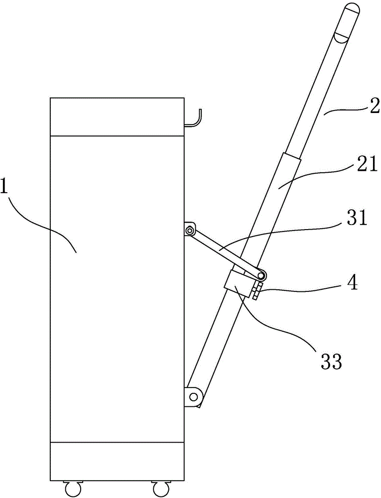
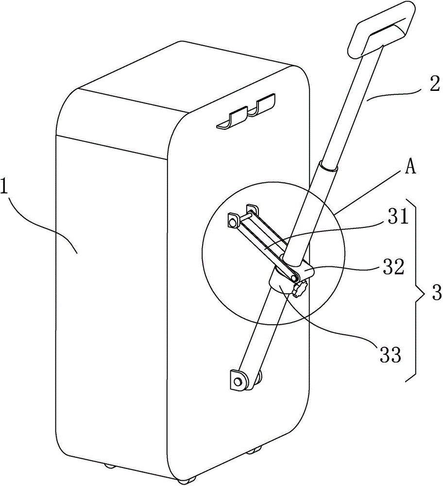
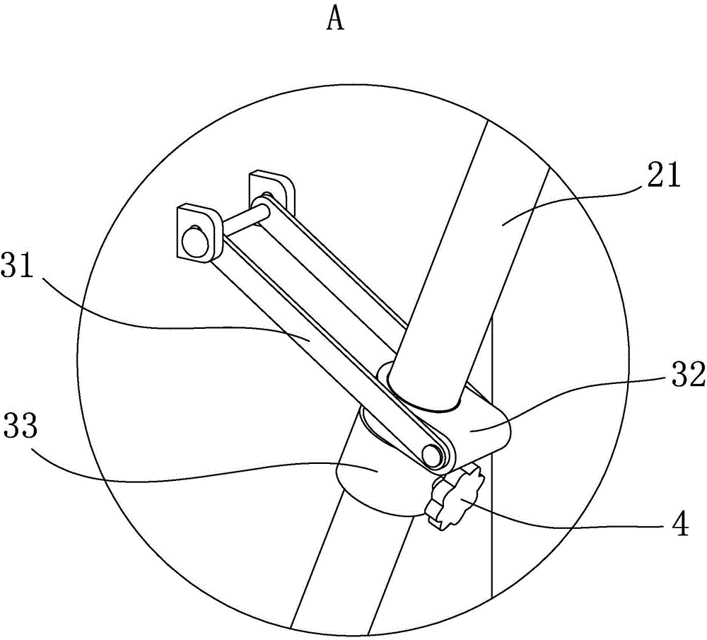
[0031] Specific implementation mode one, refer to Figures 1 to 4 , the fixed angle device 3 that this suitcase adopts comprises connecting rod 31, slide block 32 and stopper 33, and described slide block 32 is sleeved on the outer rod sleeve 21 and can move up and down along outer rod sleeve 21, and one end of connecting rod 31 Hinged on the slider 32, the other end is hinged on the side of the box body 1, and the stopper 33 is arranged on the outer rod sleeve 21 to block the downward movement of the slider 32; when the slider 32 moves to contact with the stopper 33, the connecting The angle formed by the rod 31 and the outer rod sleeve 21 below the block 33 is not less than 90 degrees. In addition, the blocking block 33 is provided with a locking device 4 that can be manually adjusted to loosen or lock the blocking block 33 and the outer rod sleeve 21, and the locking device 4 adopts a locking handwheel.
[0032] When in use, the push-pull rod 2 is pulled outward, and the s...
specific Embodiment approach 2
[0033] Specific implementation mode two, refer to Figure 5 , this specific embodiment two adopts two push-pull rods 2 that are arranged side by side, and its top is connected together with the handle, and the box body 1 is provided with the angle-fixing device 3 corresponding to each push-pull rod 2, and the angle-fixing device 3 As in the first embodiment, the two connecting rods 31 are connected together through a rotating shaft passing through the slider 32, so that the two can move up and down synchronously. The process of using and putting away is the same as that of the specific embodiment one.
specific Embodiment approach 3
[0034] Specific implementation mode three, refer to Figure 6 and Figure 7 , the fixed angle device 3 that this suitcase adopts comprises connecting rod 31, fixed block 34 and slide rail 35, and described fixed block 34 is arranged on the outer rod cover 21, and slide rail 35 is arranged on the side of box body 1, and described connecting rod One end of 31 is movably connected up and down with slide rail 35 and can rotate around the joint, and the other end is hinged with fixed block 34; The angle formed by the sides of the box body 1 is not less than 90 degrees. In addition, the fixing block 34 is provided with a locking device 4 that can be manually adjusted to loosen or lock the fixing block 34 and the outer rod sleeve 21 . This locking device 4 adopts locking handwheel.
[0035]When in use, the push-pull rod 2 is pulled outward, and the connecting rod 31 moves down under the pull of the slider 32. When the connecting rod 31 moves to the side of the box body 1 and is ve...
PUM
 Abstract
Description
Claims
Application Information
 - R&D
- Intellectual Property
- Life Sciences
- Materials
- Tech Scout
- Unparalleled Data Quality
- Higher Quality Content
- 60% Fewer Hallucinations
Browse by: Latest US Patents, China's latest patents, Technical Efficacy Thesaurus, Application Domain, Technology Topic, Popular Technical Reports.
© 2025 PatSnap. All rights reserved.Legal|Privacy policy|Modern Slavery Act Transparency Statement|Sitemap|About US| Contact US: help@patsnap.com