Clothes display case

A technology for display cabinets and clothing, applied in the field of display cabinets, can solve problems such as structure, single function, lack of visual impact, and inability to better bring out the distinct feelings and strong impressions of clothing

Active Publication Date: 2015-03-25
JIAXING VOCATIONAL TECHN COLLEGE
View PDF5 Cites 22 Cited by
  • Summary
  • Abstract
  • Description
  • Claims
  • Application Information

AI Technical Summary

Problems solved by technology

[0003] At present, the structure and function of the clothing display cabinets that people generally see are single, lack of visual impact, and cannot better set off the clothing to leave a clear feeling and strong impression in the minds of customers.

Method used


Image

  • Clothes display case
  • Clothes display case
  • Clothes display case

Examples


Embodiment 1

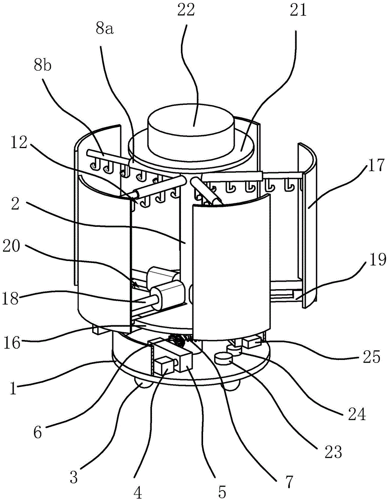
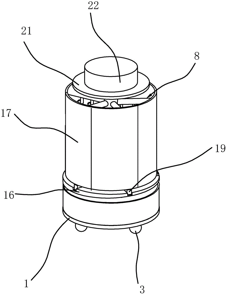
[0030] like figure 1 and figure 2 As shown, a clothing display cabinet includes a base 1 and a column 2 arranged on the base 1, wherein a retaining ring is also fixed on the base. The column 2 is hollow, and the interior of the column 2 is fixed with a number of LED lamps, which are made of transparent materials, and the bottom of the base 1 is provided with a number of universal wheels 3 .

[0031] Specifically, the lower end of the column 2 is rotatably arranged on the base 1 through a bearing, and a rotating mechanism capable of driving the column 2 to rotate on the base 1 is provided between the base 1 and the lower part of the column 2 . Wherein, the rotating mechanism includes a rotating motor 4 and a speed reducer 5 . Both the rotating motor 4 and the reducer 5 are fixed on the base 1, the output shaft of the rotating motor 4 is fixedly connected with the input shaft of the reducer 5 through a coupling, and the output shaft of the reducer 5 is fixed with a driving be...

Embodiment 2

[0037] The structure and principle of this embodiment are basically the same as that of the first embodiment, the difference is that in the first embodiment, the rotating mechanism includes a rotating motor 4 and a speed reducer 5; and in the second embodiment, as Figure 4 As shown, the rotating mechanism includes a rotating motor 4 , a main gear 26 , a slave gear 27 and a connecting gear 28 . The rotating motor 4 is fixed on the base 1, and the output shaft of the rotating motor 4 is vertically upward, the main gear 26 is fixed on the output shaft of the rotating motor 4, the slave gear 27 is fixed at the bottom of the column 2, and the connecting gear 28 is all rotated The shaft 29 and the bearing are rotatably arranged on the base 1, and the main gear 26, the slave gear 27 and the connecting gear 28 are all engaged with each other. The rotating motor 4 drives the main gear 26 to rotate, and after being decelerated by the connecting gear 28, the column 2 fixed on the slave ...

Embodiment 3

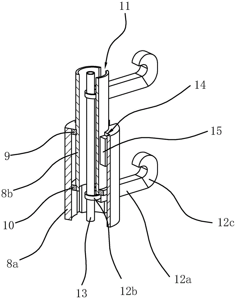
[0039] The structure and principle of this embodiment are basically the same as that of the first embodiment, the difference is that in the first embodiment, the telescopic mechanism includes a number of push cylinders 18; and in the second embodiment, the telescopic mechanism includes a number of push rod motors, The push rod motors are all fixed on the cabinet bottom plate 16, the output shaft of the push rod motor is horizontally arranged and the end of the output shaft is fixed on the cabinet wall 17. The ring 12b of the hook 12 is set in the chute 11 of the clothes hanger 8, and the ring 12b is sleeved on the chain 13, so that when the clothes hanger 8 is stretched, the hook 12 can be evenly distributed on the clothes hanger 8 .


PUM


Abstract

The invention provides a clothes display case and belongs to the technical field of display cases. The clothes display case solves the problems that clothes cannot be conveniently displayed through a clothes display case in the prior art. The clothes display case comprises a base and a stand column, wherein a rotating mechanism is arranged between the base and the lower portion of the stand column, clothes hanging rods are fixed to the upper portion of the stand column, each clothes hanging rod is composed of a fixed rod body and a sliding rod body, one end of each fixed rod body is fixed to the stand column, the other end of each fixed rod body is provided with a blocking edge, a case wall is fixed to one end of each sliding rod body, a blocking shoulder is arranged at the other end of each sliding rod body, sliding grooves are formed in the sliding rod bodies and the fixing rod bodies, hooks are arranged in the sliding grooves, a case bottom plate is arranged on the stand column, a telescopic mechanism is further arranged between the case walls and the case bottom plate, a case top plate is fixed to the upper end of the stand column, and an LED advertisement display screen is fixed to the case top plate. The visual effect of clothes can be provided for customers in a more user-friendly mode, and therefore the clothes display efficiency is improved.

Description

technical field [0001] The invention belongs to the technical field of display cabinets, and relates to a clothing display cabinet. Background technique [0002] The display cabinet is the main carrier for expressing goods in commerce, and it is also the main frame that constitutes the vision of commercial space. Different commodities require display cabinets with different shapes and functions. The function of the clothing display cabinet is mainly to attract and attract customers to the greatest extent through its own structure and auxiliary facilities, stimulate customers' emotions, and mobilize their desire to buy. [0003] At present, the structure and function of the clothing display cabinets that people generally see are single, lack of visual impact, and cannot better set off the clothing to leave a clear feeling and strong impression in the minds of customers. [0004] Due to the above-mentioned problems, those skilled in the art have yet to develop a display cabi...

Claims


Application Information

Patent Timeline
Patent Type & Authority Applications(China)
IPC IPC(8): A47F7/19A47F7/26A47F3/11
CPCA47F3/11A47F7/19A47F7/26
Inventor 肖雯杨俊缪晓燕张青夏
Owner JIAXING VOCATIONAL TECHN COLLEGE
Why Eureka
Try Eureka