
Conjoined drain opening lift type headrest bath barrel

A drainage port and lift-type technology, applied in the field of bath barrels, can solve the problems of difficult drainage of water, poor versatility, and inability to apply to people of different heights, etc.

Inactive Publication Date: 2015-03-25
台州市黄岩振荣塑料厂
View PDF6 Cites 3 Cited by
  • Summary
  • Abstract
  • Description
  • Claims
  • Application Information

AI Technical Summary

Problems solved by technology

Children sit in the tub to take a bath, and most of their body is soaked in the water. The existing tub is vertical due to the height of the tub wall, and the head of the child is forward. etc., there is a security risk
Therefore the applicant once applied for the Chinese patent "Children's Bathing Container with Safety Headrest", the patent number is ZL201420065983. Manufactured in one piece with the body, the height of the headrest cannot be adjusted, and it cannot be used for people of different heights. The hole is directly connected to the drainpipe, so that the drainpipe is bent and folded, and the water in the container is not easy to discharge. However, the existing common structure is that a connecting seat is made at the bottom of the container, and there are screw holes on the outer wall around the connecting seat. One end is connected to a 90° connecting elbow, and the outer wall of the connecting elbow is provided with screws. The connecting elbow is inserted into the connecting seat, and then connected to the screw hole through the screw. The structure is complex, the mold development cost is high, and a gasket needs to be installed at the joint , sealing ring and other sealing structures have high requirements for sealing and are troublesome to install and disassemble

Method used


Image

  • Conjoined drain opening lift type headrest bath barrel
  • Conjoined drain opening lift type headrest bath barrel
  • Conjoined drain opening lift type headrest bath barrel

Examples


Embodiment Construction

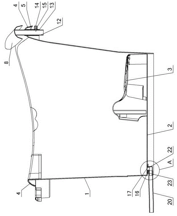
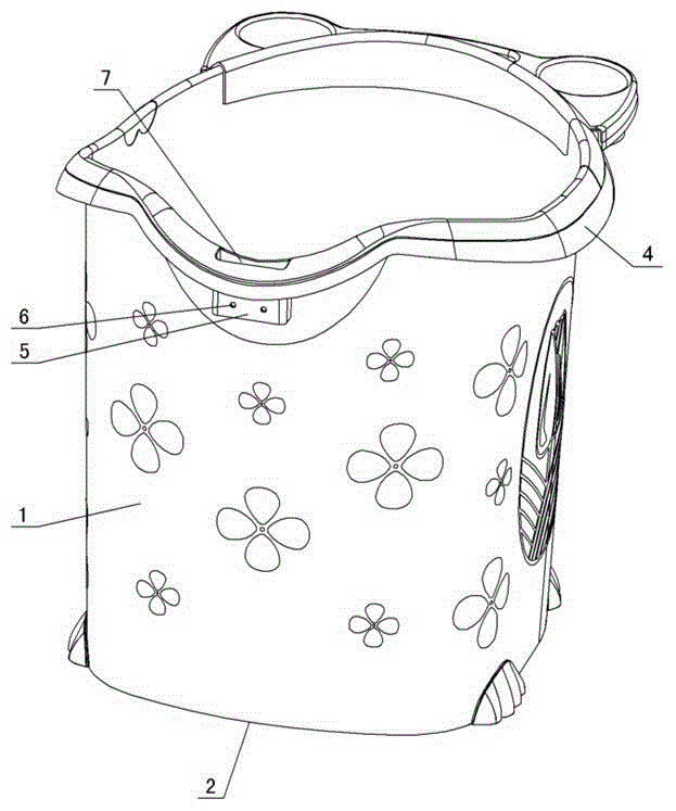
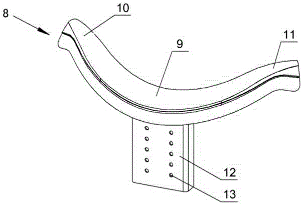
[0011] The present invention relates to a one-piece drain outlet lifting type headrest bath bucket, such as figure 1 — Figure 4 As shown, it includes a barrel body 1 and a barrel bottom 2, a base 3 is set on the barrel bottom, and a drain port 16 is formed at the bottom of the barrel. An insertion ring 5 is formed under the flange on the rear side of the head, and a card hole 6 is formed on the wall of the insertion ring. An insertion hole 7 is formed in the insertion ring, and a lifting type headrest is arranged in the insertion hole. The lifting type headrest includes The headrest body 8 is formed with an insertion rod 12 under the headrest body 8, an adjustment hole 13 is formed on the insertion rod, a positioning block 14 is arranged on the outer wall of the insertion ring 5, and a positioning pin 15 is formed on the positioning block, and the positioning pin passes through the socket 7 is matched with the adjustment hole 13, and the drain port 16 of the bucket bottom 2 ...


PUM


Abstract

A conjoined drain opening lift type headrest bath barrel comprises a barrel body and a barrel bottom. A base is arranged on the barrel bottom, and a drain opening is formed in the barrel bottom. The conjoined drain opening lift type headrest bath barrel is characterized in that a flanging is arranged on an upper opening of the barrel body, an inserting ring is arranged below the flanging on the rear side of the opening of the barrel body, a clamping hole is formed in the wall of the inserting ring, an inserting hole is formed in the inserting ring, a lift type headrest is arranged in the inserting hole, the lift type headrest comprises a headrest body, an inserting rod is arranged below the headrest body, an adjusting hole is formed in the inserting rod, a positioning block is arranged on the outer wall of the inserting ring, a positioning pin is arranged on the positioning block, the positioning pin penetrates through the inserting hole to be matched with the adjusting hole, and the drain opening in the barrel bottom comprises a bend or a straight tube which is integrally formed with the barrel bottom; the bend or the straight tube is connected with a drain tube, and a sealing plug is arranged at an upper opening part of the bend or the straight tube.

Description

technical field [0001] The invention relates to a bath tub, in particular to a one-piece drain outlet lifting type headrest bath tub. Background technique [0002] Children (including young children) generally like to sit or stand in hot water to take a bath, and usually need help from adults, so it is more suitable to use a movable bath container, which is different from the existing bath tub (referring to the large-mouthed shallow basin suitable for It is better to lie down and take a bath), has a higher wall, and is generally called a bath barrel or a bath barrel. Children sit in the tub to take a bath, and most of their body is soaked in the water. The existing tub is vertical due to the height of the tub wall, and the head of the child is forward. etc., there are security risks. Therefore the applicant once applied for the Chinese patent "Children's Bathing Container with Safety Headrest", the patent number is ZL201420065983. Manufactured in one piece with the body, ...

Claims


Application Information

Patent Timeline
IPC IPC(8): A47K3/024
Inventor 徐道永
Owner 台州市黄岩振荣塑料厂
Learn More