Unloading mechanism of bottle blowing machine

A bottle blowing machine and feeding technology, applied in the field of bottle blowing machines, can solve the problems of short service life and high cost, and achieve the effect of long service life and cost saving

Active Publication Date: 2017-04-12
章超超
View PDF6 Cites 0 Cited by
  • Summary
  • Abstract
  • Description
  • Claims
  • Application Information

AI Technical Summary

Problems solved by technology

[0005] In order to overcome the disadvantages that the feeding method of the existing bottle blowing machine cannot be applied to ultra-deep cavities, heavy bottles are automatically unloaded, the cost is high, and the service life is short. Automatic unloading of heavy bottles, cost-saving, and long-lasting blow molding machine unloading mechanism

Method used


Image

  • Unloading mechanism of bottle blowing machine
  • Unloading mechanism of bottle blowing machine
  • Unloading mechanism of bottle blowing machine

Examples


Embodiment Construction

[0023] The present invention will be further described below in conjunction with the accompanying drawings.

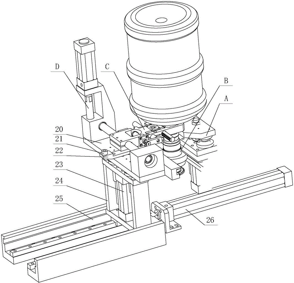
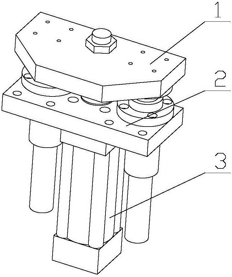
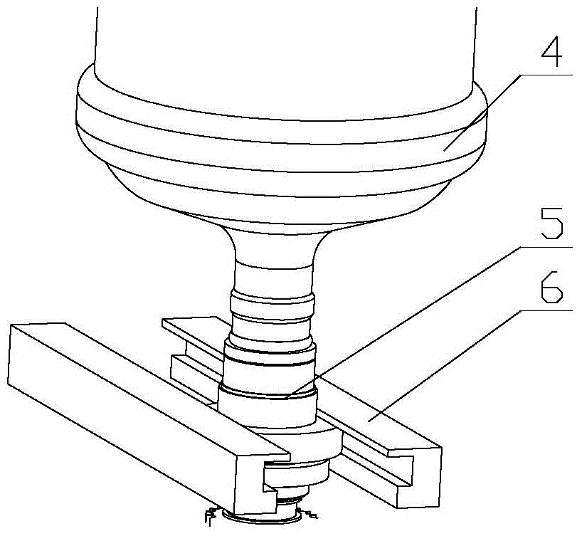
[0024] refer to Figure 1 to Figure 8 , a blanking mechanism of a bottle blowing machine, including a frame and a manipulator, a lifting frame 24 can be slidably installed on the frame, a platform 20 can be installed up and down on the lifting frame 24, and a platform 20 can be rotated The rotating shaft 15 is installed firmly, and the rotating shaft 15 is connected with the rotating drive assembly for driving the rotating shaft 15 to rotate. The manipulator seat 13 is fixedly installed on the rotating shaft 15, and the manipulator includes a left finger 11 and a right finger 10, so The rear parts of the left finger 11 and the right finger 10 are provided with a front mounting hole and a rear mounting hole from front to rear, and the connection line between the front mounting holes and the connection line between the rear mounting holes are respectively parallel to the...


PUM


Abstract

The invention discloses a discharging mechanism of a bottle blowing machine. The discharging mechanism comprises a rack and a manipulator, wherein a lifting frame is arranged on the rack in a slidable manner, a platform is arranged on the lifting frame in an up-down lifting manner, a rotating shaft is rotatably arranged on the platform and connected with a rotating drive assembly, a manipulator base is fixedly arranged on the rotating shaft, front installing holes and rear installing holes are both formed in the rear parts of a left finger and a right finger from front to rear, a connecting line between the front installing holes and a connecting line between the rear installing holes are respectively in parallel with the rotating shaft, a long rack penetrates through the front installing holes of the left finger and the right finger, a short rack penetrates through the rear installing holes of the left finger and the right finger, an opening and closing gear is rotatably arranged in the manipulator base between the short rack and the long rack, the front side of the opening and closing gear is meshed with the long rack, the rear side of the opening and closing gear is meshed with the short rack; the long rack or short rack is connected with an opening and closing drive assembly, and the opening and closing drive assembly is arranged in the manipulator base. The discharging mechanism is effectively suitable for automatically discharging a bottle with an ultra-deep cavity and large weight, cost-saving, and long in service life.

Description

technical field [0001] The invention relates to a bottle blowing machine, in particular to a feeding mechanism of the bottle blowing machine. Background technique [0002] Existing bottle blowing machine comprises preform conveying mechanism, feeding mechanism, heating oven mechanism, mold clamping mechanism and unloading mechanism; Described preform conveying mechanism adopts ring chain usually, and the arrangement bottle of equal interval on the ring chain The blank seat, on the side of the endless chain, arranges a feeding mechanism, a heating oven mechanism, a mold clamping mechanism and a feeding mechanism in sequence according to the running direction. [0003] Existing fully automatic blow molding machines are only suitable for preforms with short length and light weight. For preforms with ultra-deep cavities such as five gallons and heavy weight, manual feeding is usually used in the prior art to place the preforms to the preform seat of the endless chain; the blank...

Claims


Application Information

Patent Timeline
Patent Type & Authority Patents(China)
IPC IPC(8): B29C49/70
Inventor 卢康东
Owner 章超超
Why Eureka
Try Eureka