Reciprocating compressor

A compressor and reciprocating technology, which is applied in the direction of liquid variable capacity machinery, mechanical equipment, electromechanical devices, etc., can solve the problems of supplying gas refrigerant, increasing compression loss, and increasing refrigerant amount, so as to improve the performance of the compressor and reduce the The effect of specific volume

Active Publication Date: 2015-03-25
LG ELECTRONICS INC
View PDF5 Cites 16 Cited by
  • Summary
  • Abstract
  • Description
  • Claims
  • Application Information

AI Technical Summary

Problems solved by technology

[0007] However, in the conventional reciprocating compressor as described above, the gas refrigerant cannot be supplied between the cylinder 2 and the piston 1 because the foreign matter mixed in the gas refrigerant flows into the gas bearing and clogs the gas bearing. The concentricity between 1 and cylinder 2 deviates and piston 1 reciprocates in a state of close contact with cylinder 2, resulting in frictional loss or wear
In particular, if the oil remaining in the refrigeration cycle is mixed with the refrigerant and flows into the gas bearing of the compressor, the gas bearing will be firmly blocked by foreign matter due to the viscosity of the oil, resulting in a decrease in the performance of the bearing.
In addition, when the oil flows between the cylinder 2 and the piston 1, foreign matter mixed in the oil sticks between the cylinder 2 and the piston 1, causing frictional loss or wear
[0008] In view of these problems, it is possible to prevent clogging by foreign matter by forming the bearing hole of the gas bearing larger. However, at this time, the compressed gas refrigerant does not flow into the refrigeration cycle and the amount of refrigerant flowing into the gas bearing increases, thereby resulting in a corresponding increase in compression loss

Method used


Image

  • Reciprocating compressor
  • Reciprocating compressor
  • Reciprocating compressor

Examples


Embodiment Construction

[0045] Hereinafter, the reciprocating compressor of the present invention will be described in detail based on an embodiment shown in the drawings.

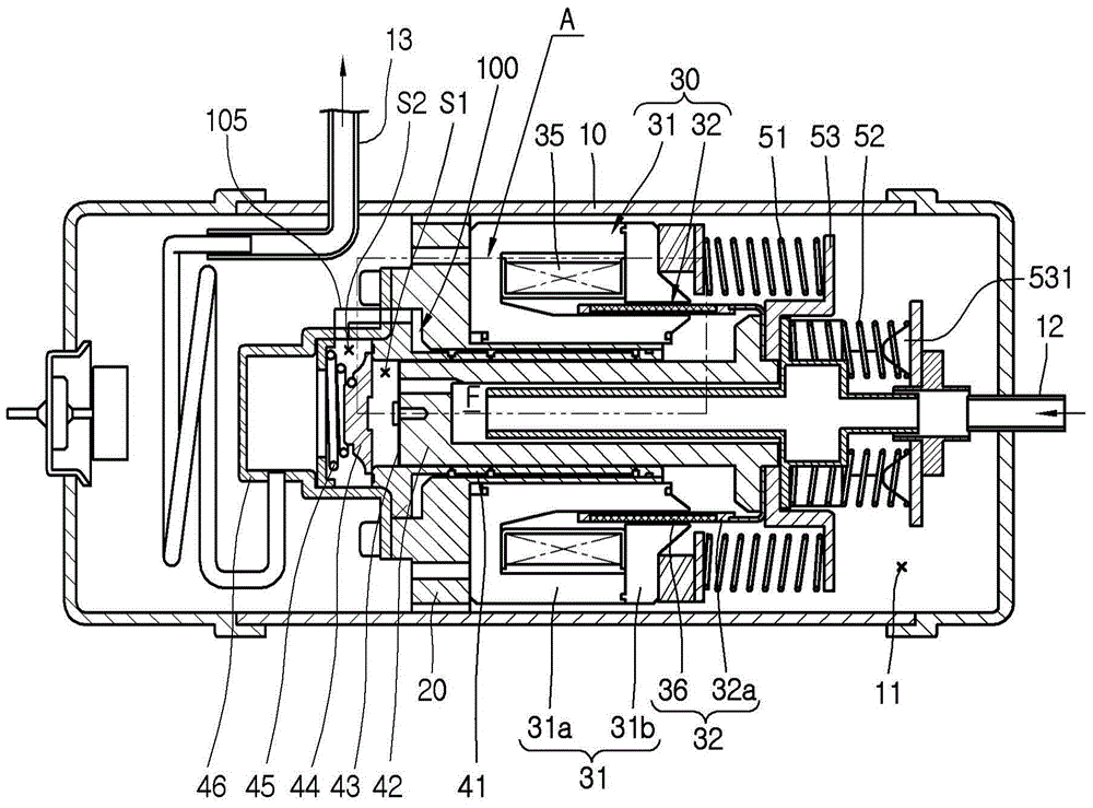
[0046] image 3 is a longitudinal sectional view showing the reciprocating compressor of the present invention.

[0047] refer to image 3 , in the reciprocating compressor of the embodiment of the present invention, the internal space of the casing 10 can be connected to the suction pipe 12 , and the discharge space S2 of the discharge cover 46 described later can be connected to the discharge pipe 13 . The inner space 11 of the casing 10 is provided with a frame 20, on which the stator 31 and the cylinder 41 of the reciprocating motor 30 are fixed, and the piston 42 combined with the mover 32 of the reciprocating motor 30 is inserted in the cylinder 41, so that The piston 42 reciprocates in the cylinder 41 , and resonant springs 51 and 52 for inducing the resonant motion of the piston 42 can be respectively provided on both s...


PUM


Abstract

Provided is a reciprocating compressor. The reciprocating compressor includes a cylinder having a compression space, a piston inserted into the cylinder to define the compression space while being reciprocated, the piston having a suction passage to communicate with the compression space, a gas bearing having a bearing hole passing through the cylinder so that a refrigerant gas is injected between the cylinder and the piston to support the piston with respect to the cylinder, and a flow resistance part disposed on an outer circumferential surface of the cylinder or one side of the cylinder to restrict a flow of the refrigerant gas flowing toward the bearing hole.

Description

technical field [0001] The present invention relates to reciprocating compressors, in particular to reciprocating compressors having gas bearings. Background technique [0002] In general, a reciprocating compressor uses a method in which a piston reciprocates linearly inside a cylinder to suck in compressed refrigerant and discharge it. Reciprocating compressors can be divided into connection type and vibration type according to the driving method of the piston. [0003] The connected reciprocating compressor adopts a method in which a piston is connected to a rotating shaft of a rotary electric machine via a connecting rod to reciprocate in a cylinder to compress refrigerant. In contrast, the vibrating reciprocating compressor uses a method in which a piston is connected to a mover (mover) of a reciprocating motor to vibrate, thereby reciprocating in a cylinder to compress refrigerant. The present invention relates to a vibratory reciprocating compressor, so the vibrator...

Claims


Application Information

Patent Timeline
Patent Type & Authority Applications(China)
IPC IPC(8): F04B39/00
CPCF04B35/045F04B39/126F04B53/008F04B39/16F04B39/0292F04B17/04F04B39/00F04B35/04H02K41/02
Inventor 崔基喆安光运金烔汉
Owner LG ELECTRONICS INC
Why Eureka
Try Eureka