Eureka AIR delivers breakthrough ideas for toughest innovation challenges, trusted by R&D personnel around the world.

Refrigerating system based on automobile engine exhaust

A refrigeration system and engine technology, applied in the direction of machines/engines, steam engine devices, steam applications, etc., can solve the problems of only 35% to 40% of the effective power of the engine, insufficient use of fuel heat energy, strong exhaust pressure of automobiles, etc., to achieve The effect of high saturation pressure, low toxicity, and large latent heat of vaporization

Inactive Publication Date: 2019-08-20
HARBIN UNIV OF SCI & TECH
View PDF4 Cites 1 Cited by
  • Summary
  • Abstract
  • Description
  • Claims
  • Application Information

AI Technical Summary

Problems solved by technology

The automobile industry has also become one of the pillar industries of the national economy. People know that the power plant of the automobile is mainly an internal combustion engine, which converts heat energy into kinetic energy through fuel to drive the automobile. However, the current level of technology cannot fully utilize the internal combustion engine to generate About 40% of the heat energy is not fully utilized, and most of it is discharged into the atmosphere through the exhaust pipe in the form of waste heat. During the combustion process of the internal combustion engine, the instantaneous temperature can reach 1800 degrees, in less than 0.1 seconds Exhausting the burned gas, the temperature of the exhaust gas in the exhaust pipe can also reach 800 degrees, and the pressure generated by the exhaust gas in the exhaust pipe is very high, and a large amount of heat energy cannot be used, causing huge economic losses and environmental damage.
In order to ensure the normal operation of the engine, the circulating cooling water takes away 30% of the calorific value of the fuel, and the outlet temperature is generally controlled at 350-500°C, the exhaust gas takes away 35%-45%, and the effective power of the engine is only 35%-40%. underutilized

Method used

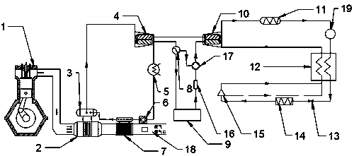
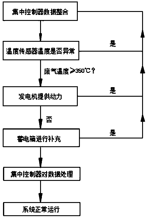

Image

  • Refrigerating system based on automobile engine exhaust
  • Refrigerating system based on automobile engine exhaust
  • Refrigerating system based on automobile engine exhaust

Examples


Embodiment Construction

[0009] A refrigeration system based on automobile engine exhaust gas works as follows:

[0010] 1. The principle of organic Rankine cycle power generation of engine exhaust gas

[0011] Main process: The organic Rankine cycle system is a process of converting waste heat into electric energy and kinetic energy. Its working principle is to use the exhaust gas exhausted by the crank linkage mechanism of the engine 1 to flow through the evaporator 2 to heat the organic working medium R134a, so that The organic working medium reaches saturation and enters the steam drum 3, enters the expander 4 to do work, part of it drives the compressor unit for refrigeration, and the other part passes through the generator 8 to generate electricity. When the temperature of the exhaust gas is low, it can be directly driven by the motor to compress 10, when the compressor 10. During normal operation, the generator can generate power to the storage box 9 for energy storage. When the engine 1 stops ...


PUM


Abstract

The invention discloses a refrigerating system applicable to automobile engine exhaust. The refrigerating system comprises an evaporator, a working medium pump, an exhaust heat regenerator, a condenser, a screw expander, a compressor, a generator, circulating pipelines, a liquid storage tank, an electric power storage tank and the like. One part takes an exhaust heat source emitted from an engineas the heat source, exhaust emitted by an automobile exhaust pipe heats an organic working medium in the liquid storage tank, the organic working medium is changed into a gaseous state from the liquidstate, then steam is introduced into the expander for acting through a steam pipe, and one part drives the compressor to perform refrigerating; and the other part is brought to the electric power storage tank for energy storage through the turbine generator, so that the compressor operates normally when the engine stops working. The refrigerating system fully recovers heat energy in the automobile exhaust, and the utilization rate is high.

Description

technical field [0001] The invention belongs to the technical field of air-conditioning technology, in particular to CO with exhaust gas from an automobile engine as a heat source. 2 Transcritical cycle refrigeration system. Background technique [0002] With the growth of the economy and the improvement of people's living standards, automobiles have become indispensable in people's daily life. The automobile industry has also become one of the pillar industries of the national economy. People know that the power plant of the automobile is mainly an internal combustion engine, which converts heat energy into kinetic energy through fuel to drive the automobile. However, the current level of technology cannot fully utilize the internal combustion engine to generate About 40% of the heat energy is not fully utilized, and most of it is discharged into the atmosphere through the exhaust pipe in the form of waste heat. During the combustion process of the internal combustion engi...

Claims


Application Information

Patent Timeline
Patent Type & Authority Applications(China)
IPC IPC(8): F01K11/02F01K7/32F01K17/04F01K27/00
CPCF01K7/32F01K11/02F01K17/04F01K27/00
Inventor 陈巨辉许滔陈纪元马明廖吉鹏徐鑫
Owner HARBIN UNIV OF SCI & TECH
Why Eureka
Eureka Blog
Learn More