
Cooling liquid path structure of transmission oil, oil cooling integration module and installation structure of oil cooling integration module

A technology of transmission oil and integrated modules, which is applied in the direction of gear lubrication/cooling, components with teeth, transmission control, etc., and can solve the problem that the cooling structure cannot meet the needs of the engine, etc.

Active Publication Date: 2015-03-25
GREAT WALL MOTOR CO LTD
View PDF5 Cites 3 Cited by
  • Summary
  • Abstract
  • Description
  • Claims
  • Application Information

AI Technical Summary

Problems solved by technology

From the perspective of engine thermal management, during the working period from cold start to warm-up of the engine, the oil temperature needs to be quickly heated to the optimum state to ensure the normal operation of the engine. However, the cooling structure of the existing oil cooler cannot meet the requirements of the engine. the practical needs of

Method used


Image

  • Cooling liquid path structure of transmission oil, oil cooling integration module and installation structure of oil cooling integration module
  • Cooling liquid path structure of transmission oil, oil cooling integration module and installation structure of oil cooling integration module
  • Cooling liquid path structure of transmission oil, oil cooling integration module and installation structure of oil cooling integration module

Examples


Embodiment Construction

[0037] It should be noted that, in the case of no conflict, the embodiments of the present invention and the features in the embodiments can be combined with each other.

[0038] The present invention will be described in detail below with reference to the accompanying drawings and examples.

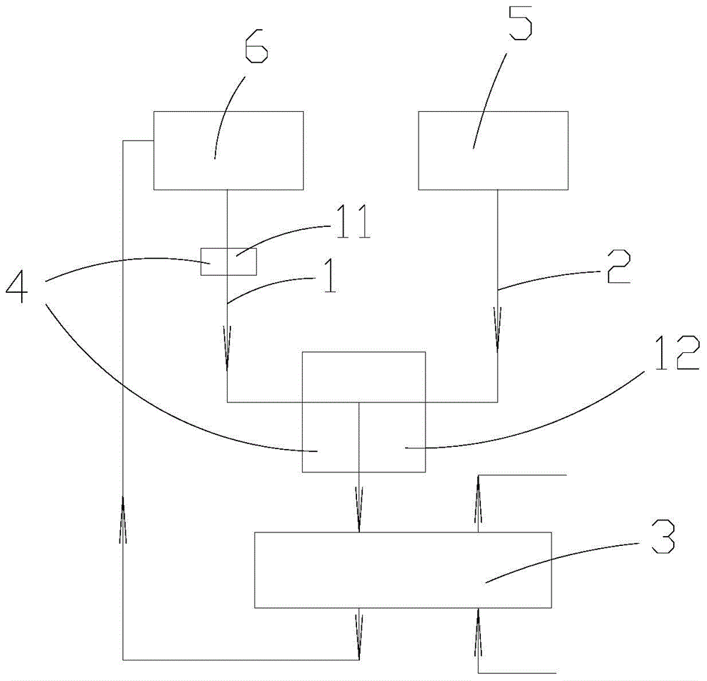
[0039] Such as figure 1 As shown, the transmission oil cooling liquid circuit structure provided by the present invention includes a cooling liquid circuit and a control valve device 4 arranged on the cooling liquid circuit, and the cooling liquid circuit includes a first cooling liquid circuit 1 and a second cooling liquid circuit 2 The water inlet of the first coolant path 1 is used to communicate with the water outlet of the engine block water jacket 6, the water inlet of the second coolant path 2 is used to communicate with the cooling water tank 5, the first coolant path 1 and the second coolant The water outlets of the road 2 are used to connect to the water inlet of the transmiss...


PUM


Abstract

The invention provides a cooling liquid path structure of transmission oil, an oil cooling integration module and an installation structure of the oil cooling integration module. The cooling liquid path structure comprises cooling liquid paths and a control valve device arranged on the cooling liquid paths, the cooling liquid paths comprise the first cooling liquid path and the second cooling liquid path, a water inlet of the first cooling liquid path is used for being communicated with a water outlet of an engine cylinder water jacket, a water inlet of the second cooling liquid path is used for being communicated with a cooling water tank, a water outlet of the first cooling liquid path and a water outlet of the second cooling liquid path are both used for being connected with a water inlet of a transmission oil cooler, the control valve device can be switched into three work states by inducing the water temperature of the engine cylinder water jacket and the temperature of the transmission oil so as to guarantee that the temperature of the transmission oil can change according to different working conditions of a vehicle and can always be in the optimal range of the corresponding working conditions, and accordingly reliability of the whole vehicle is improved.

Description

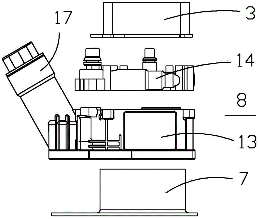
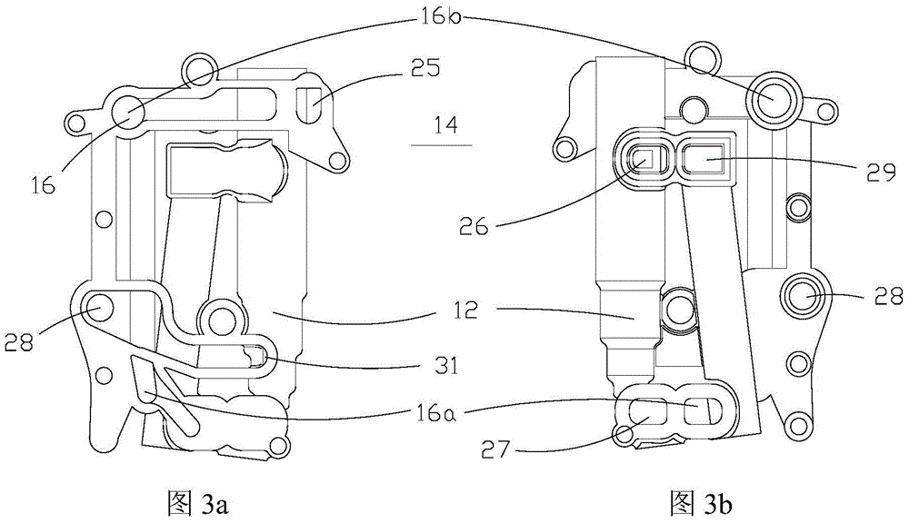
technical field [0001] The invention relates to the technical field of vehicle oil cooling, in particular to a transmission oil cooling liquid circuit structure, an oil cooling integrated module including the cooling liquid circuit structure and used for cooling engine oil and transmission oil, and a transmission oil cooling circuit structure. The installation structure of the oil cooling integrated module. Background technique [0002] Whether the cooling and lubrication performance of the vehicle's engine and transmission is good directly affects the fuel economy, emission performance, reliability and service life of the engine. [0003] Considering the overheating problem of transmission oil, the existing design usually takes water from the engine cooling circulation water circuit to cool the transmission oil, and after cooling, the coolant returns to the engine water inlet. However, the existing design only considers the working conditions of the engine when it is runni...

Claims


Application Information

Patent Timeline
Patent Type & Authority Applications(China)
IPC IPC(8): F16H57/04F16H61/4165
CPCF16H57/04F16H61/4165
Inventor 鲍春来王江涛龙艳中贺礼耿齐月张翠翠张士伟
Owner GREAT WALL MOTOR CO LTD
Learn More