Information acquisition device mounting base

A technology of information collection and mounting seat, which is applied in the direction of supporting machines, mechanical equipment, machine platforms/supports, etc., can solve the problems of single structure and function of the support, inconvenience for ordinary consumers, etc., and achieve easy manufacturing and assembly, simple structure and high efficiency The effect of installation

Active Publication Date: 2015-03-25
双环传动(嘉兴)精密制造有限公司
View PDF5 Cites 4 Cited by
  • Summary
  • Abstract
  • Description
  • Claims
  • Application Information

AI Technical Summary

Problems solved by technology

[0004] In order to ensure the safe operation of the "digital urban community service platform" mentioned above, cameras for information collection or input are usually installed in stores. When the angle needs to be adjusted, there are many inconvenient problems for ordinary consumers. The invention provides an information collection device mounting seat

Method used


Image

  • Information acquisition device mounting base
  • Information acquisition device mounting base
  • Information acquisition device mounting base

Examples


Embodiment 1

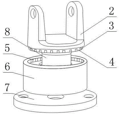
[0026] like figure 1 , figure 2 and image 3 As shown, a mounting seat for an information collection device includes a mounting plate 7 and a mounting portion provided on the mounting plate 7 for camera installation, the mounting portion includes a wheel base 6 and a rotatable rotating frame 2;

[0027] The lower end of the runner seat 6 is fixedly connected to the mounting plate 7, the runner seat 6 is provided with an annular turning groove 5, and the side wall surface of the turning groove 5 is provided with a plurality of tooth grooves;

[0028] The rotating frame 2 is provided with a runner 4 whose outer diameter matches the diameter of the rotating groove 5, and the rotating wheel 4 is provided with at least one cog to cooperate with the tooth groove to prevent the rotating wheel 4 from rotating in the rotating groove 5. anti-rotation part;

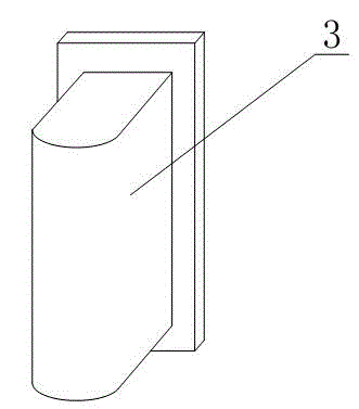
[0029] The anti-rotation part includes a limit plate 3 and a spring 1. The runner 4 is provided with a spring groove, and the ...

Embodiment 2

[0033] The present embodiment is further limited on the basis of embodiment 1, as figure 1 , figure 2 and image 3 As shown, in order to realize the 5360° rotation of the swivel frame 2 around the swivel groove, the side surfaces of the tooth grooves around the swivel groove 5 are evenly distributed in a ring shape.

[0034] In order to optimize the stress on the spring 1 when the runner 4 rotates in the rotary groove 5 and prolong the life of the spring 1 , the axial direction of the spring 1 is located in the radial direction of the runner 4 . That is, the stressed direction of the spring 1 in the above arrangement is located on its axial direction.

[0035] In order to realize the fixing of the rotating frame 2 and the runner seat 6 through the cooperation of the limiting plate 3 and the tooth groove, the two ends of the tooth groove are located between the opening end and the bottom end of the rotating groove 5 .

[0036] In order to optimize the stability of the rotat...

Embodiment 3

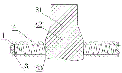
[0038] This embodiment is further limited on the basis of the above embodiments, as figure 1 , figure 2 and image 3 As shown, in order to prevent the rotating frame 2 from falling off from the runner seat 6 due to improper operation by the operator, as a simple structural form, the equal-diameter section 83 is provided with external threads, and the runner seat 6 is provided with The shaft hole of the equal-diameter section 83 clearance fit, the axes of the positioning rod 8, the runner 4 and the shaft hole are collinear, the equal-diameter section 83 is penetrated in the shaft hole, and the free end of the rotating shaft 8 is also threaded. It is used to limit the nut of the position of the runner seat 6 on the positioning rod 8 .


PUM


Abstract

The invention discloses an information acquisition device mounting base. The information acquisition device mounting base comprises a mounting plate and a mounting part arranged on the mounting plate. The mounting part comprises a rotary wheel seat and a rotary frame, wherein the rotary wheel seat is provided with a circular-ring-shaped rotary groove, and the side wall face of the rotary groove is provided with multiple tooth grooves; the rotary frame is provided with a rotary wheel, and the rotary wheel is provided with at least one anti-rotating part; the anti-rotating part comprises a limit plate and a spring; the rotary wheel is provided with a spring groove; a locating rod is further arranged on the rotary frame in a threaded connection mode; the locating rod comprises a threaded section, a variable-diameter section and an equal-diameter section; the center of the rotary wheel is provided with a threaded hole, the side face of the limit plate is a smooth face, and the limit plate protrudes relative to the side face of the rotary wheel. The information acquisition device mounting base is simple in structure and convenient to process and manufacture, an operator can adjust the facing direction of the rotary frame conveniently and easily, the facing direction of a camera can be adjusted by any tenderfoot, the optimal shooting or information recording effect can be achieved conveniently, and meanwhile the adjustment range of the facing direction of a reading device is large.

Description

technical field [0001] The invention relates to the field of information collection equipment for community self-service payment stores, in particular to an information collection device mounting seat. Background technique [0002] The "Digital City Community Service Platform" project is a new e-commerce service platform integrating information flow, logistics, capital flow and emerging media. Comprehensively use network and digital communication technology, integrate community public service functions, build a public technology platform suitable for the characteristics of Chinese communities, and provide shopping, air tickets, lottery tickets, stocks, hotel reservations, telephone, water and electricity, and property payment in public places and people's living communities , grocery shopping and real estate, tourism, traffic maps, policy and regulation information inquiries, advertising and other comprehensive services. Realize the infrastructure construction of digital ci...

Claims


Application Information

Patent Timeline
Patent Type & Authority Applications(China)
IPC IPC(8): F16M11/06F16M11/18F16M11/16
Inventor 李辉杜恩厚
Owner 双环传动(嘉兴)精密制造有限公司
Why Eureka
Try Eureka