Butterfly valve

A technology of rotating baffles and throttle valves, which is applied in the direction of lifting valves, valve details, valve devices, etc., can solve the problems of unsealed seals, uneven use of rubber seals, etc., and achieve the effect of simple assembly and material saving

Inactive Publication Date: 2006-08-02
ALFA LAVAL LKM
View PDF1 Cites 0 Cited by
  • Summary
  • Abstract
  • Description
  • Claims
  • Application Information

AI Technical Summary

Problems solved by technology

Variable axial forces transmitted to the rubber seal due to, for example, vibration can adversely lead to uneven utilization of the rubber seal
This may in turn lead to defects that cause the seal to beco

Method used


Image

  • Butterfly valve
  • Butterfly valve
  • Butterfly valve

Examples


Embodiment Construction

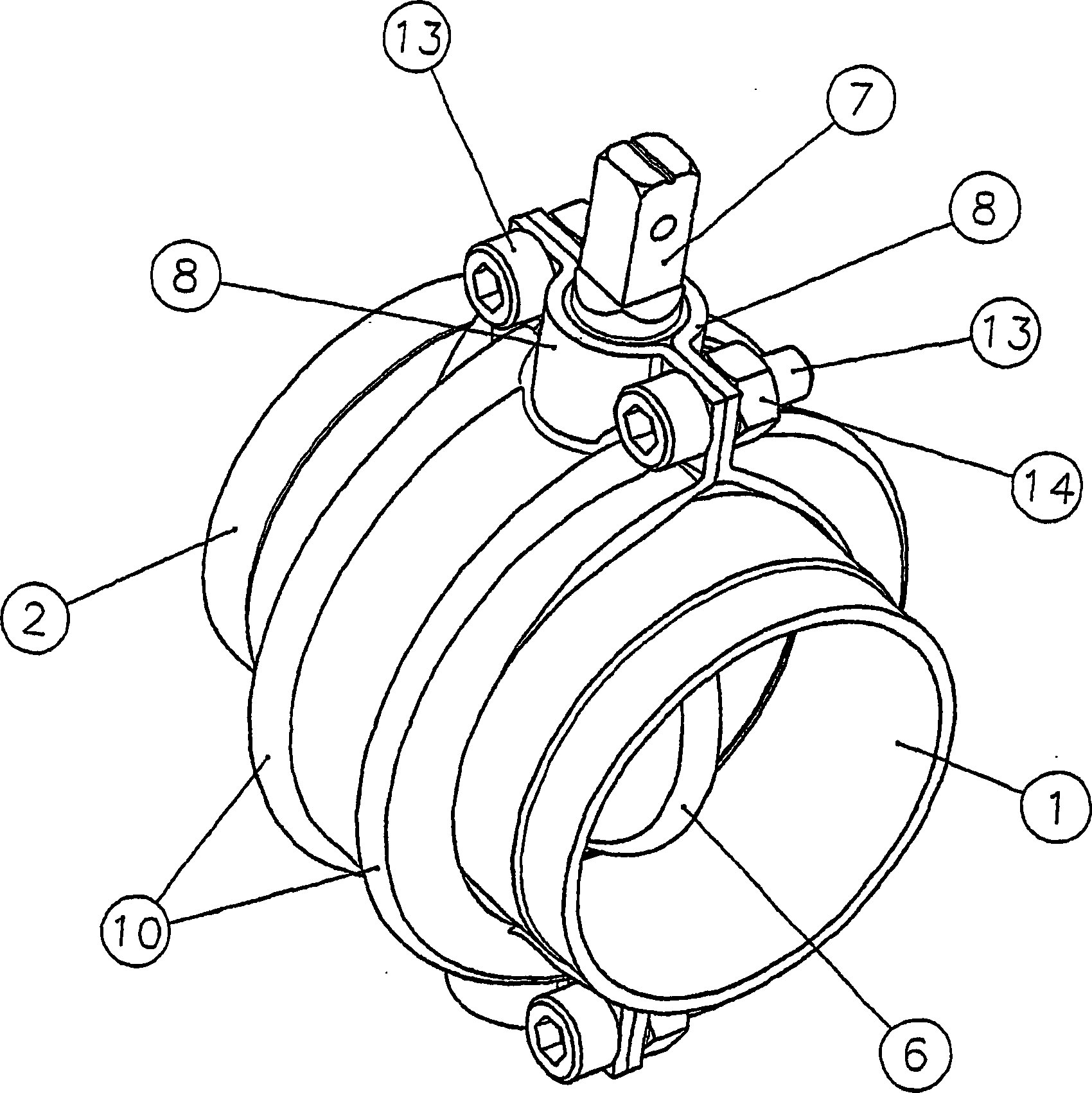
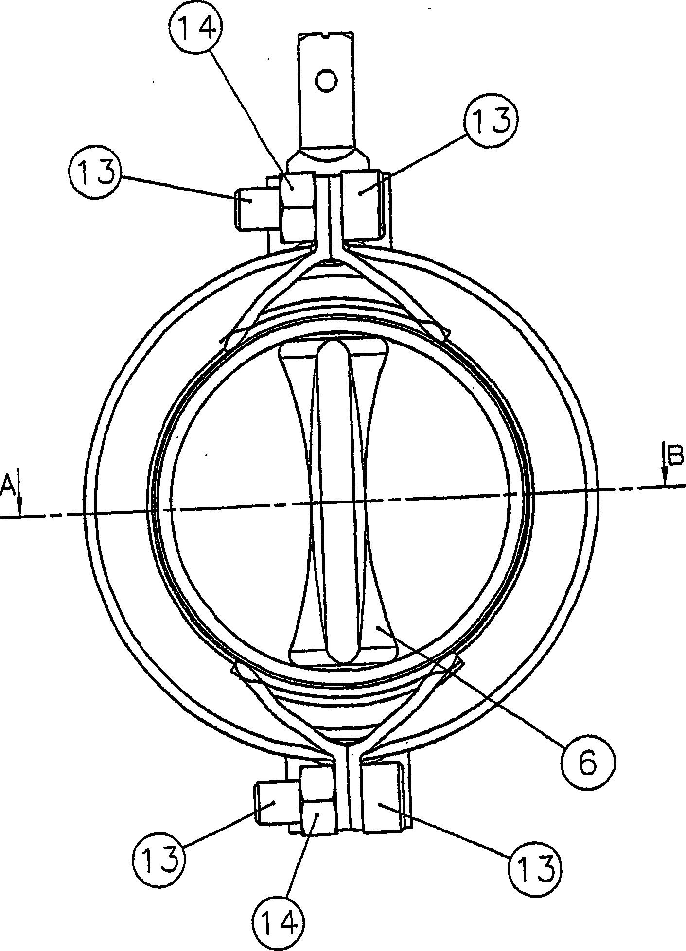
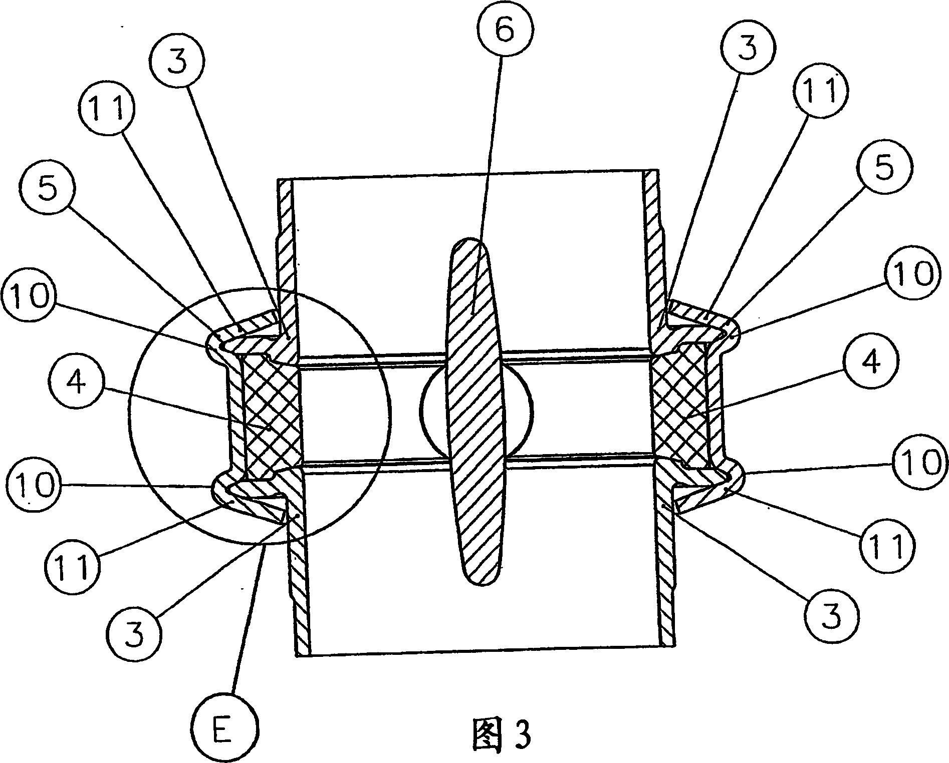
[0024] figure 1 and Figure 4 A general view of a rotary flap throttle valve according to the invention is shown obliquely from above or from the side. As can be seen in the drawing, the valve is formed from a valve inlet part 1 and a valve outlet part 2 . The valve inlet part 1 and the valve outlet part 2 are each provided with a flange 3 , the outer surfaces 15 of which are pressed axially onto the rubber seal 4 via the clamping halves 5 . The rubber seal 4 rests on the valve disk 6 . The valve disk 6 is mounted rotatably via a valve disk rod 7 on a bushing 9 which is inserted into an annular receptacle 8 of the clamping half 5 .

[0025] As can be seen from FIGS. 3 and 1 , the clamping halves 5 are each formed with two annular recesses 10 concentric with the mounting seat of the flange 3 . The recess 10 is beveled at an edge 11 . The flange 3 has a conical taper 12 outwardly. The flange 3 is rigidly connected to the clamping half 5 at its inner and outer contact surfa...


PUM


Abstract

Disclosed is a butterfly valve comprising an annular, elastic sealing element (4) that encloses an axial opening, a valve disk (6) which is disposed inside the axial opening so as to be rotatable transversal to the axial direction, means for rotating the valve disk (6) between closed and open positions in order to control a fluid flow through the opening, at least two valve housing parts (5) that enclose the sealing element (4) in an annular manner and embrace two flanges (3) which are connected to an inlet and an outlet. Conical contact areas of said flanges (3) and/or the valve housing parts (5) cooperate in such a way that the flanges (3) are axially pressed in a sealing fashion against the sealing element by means of the valve housing parts (5) in the operationally mounted state. In order to improve said butterfly valve regarding negative effects of the axial forces acting upon the sealing element (4), the flanges are respectively connected in a rigid and positive manner to a couple of clamps (5).

Description

technical field [0001] The invention relates to a rotary flapper throttle valve, which has: a substantially annular, elastic seal, which surrounds an axial opening; Disc set; mechanism for rotating the disc between an open position and a closed position to control flow of liquid through an orifice; at least two substantially annular housing members enclosing a seal enclosing two and one inlet See a flange connected to an outlet, wherein the flange and / or the conical abutment surface of the valve housing part cooperate in such a way that the flange seals axially through the valve housing part in an assembled state ready for operation Press against the seal. Background technique [0002] Such a rotary flap throttle is known, for example, from DE 15 50 499 B2. In the valve proposed there, two flanges connected to an inlet piece and an outlet piece are held together by two clamping pieces. An essentially annular rubber seal, which surrounds a valve disk, is clamped between th...

Claims


Application Information

Patent Timeline
IPC IPC(8): F16K1/226
CPCF16K1/2263F16K27/0218F16K1/2265
Inventor 考尔夫·M·拉塞
Owner ALFA LAVAL LKM
Why Eureka
Try Eureka