Backlight module and spraying jig

A technology of backlight module and backlight assembly, applied in optics, light source, shading, etc., can solve the problems of narrow double-sided tape width, affecting the frame size of display products, etc., and achieve the effect of solving complex process and improving optical taste.

Active Publication Date: 2015-03-25
TCL CHINA STAR OPTOELECTRONICS TECH CO LTD
View PDF4 Cites 5 Cited by
  • Summary
  • Abstract
  • Description
  • Claims
  • Application Information

AI Technical Summary

Problems solved by technology

In traditional product design, black double-sided adhesive is usually pasted on the surface of the backlight to fix the display panel. Since the black double-sided adhesive is a colloid with a base material, it needs to be cut mechanically and manually after cutting. Or mechanical attachment, resulting in the width of the double-sided tape cannot be extremely narrow; if it is too narrow, it cannot be cut or attached, thus affecting the frame size of the display product

Method used


Image

  • Backlight module and spraying jig
  • Backlight module and spraying jig
  • Backlight module and spraying jig

Examples


Embodiment 1

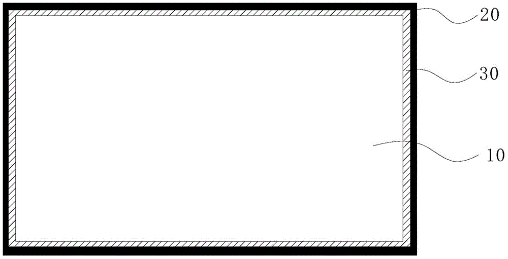
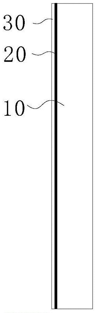
[0019] refer to figure 1 with figure 2 The present invention provides a backlight module, including a backlight assembly 10 for generating backlight, the upper surface of the backlight assembly 10 is an optical film, and a layer of light-shielding layer 20 is sprayed around the upper surface of the optical film.

[0020] The light-shielding layer 20 is formed on the periphery of the uppermost layer of the optical film of the backlight assembly 10 for absorbing excess light generated around the backlight assembly 10, eliminating light pollution and avoiding highlight areas.

[0021] In order to paste the liquid crystal panel on the backlight assembly 10 , a transparent double-sided adhesive layer 30 is provided adjacent to the inner side of the light-shielding layer 20 on the upper surface of the optical film. Wherein, the double-sided adhesive layer 30 is OCA (Optically Clear Adhesive, solid transparent optical adhesive) or OCR (Optical Clear Resin, liquid transparent optica...

Embodiment 2

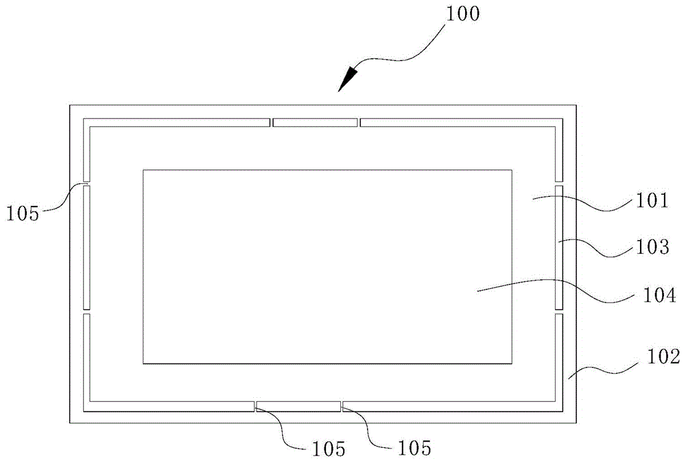
[0024] Such as image 3 In order to improve the spraying accuracy and spraying efficiency of the light-shielding layer 20, the present invention also provides a spraying fixture 100, including a rectangular first shutter 101 and a second shutter 102, the second shutter 102 is a frame structure, The external dimension of the second shutter 102 is larger than that of the backlight assembly 10, and the first shutter 101 is located in the second shutter 102, and the first shutter 101 and the second shutter 102 are connected by a plurality of connecting bars 105 to form a The interval groove 103 between the plate 101 and the second shutter 102 can be sprayed through the interval groove 103 .

[0025] A plurality of connecting bars 105 are arranged at intervals between the first shroud 101 and the second shroud 102 for connecting the two, and divide the interval groove 103 into a plurality of isolated groove areas.

[0026] At the same time, in order to reduce the manufacturing cos...


PUM


Abstract

The invention discloses a backlight module which comprises a backlight module body used for generating a backlight source. An optical membrane is arranged on the upper surface of the backlight module body, and a light shielding layer is sprayed on the periphery of the upper surface of the optical membrane. According to the backlight module, due to the fact that the light shielding layer is sprayed on the periphery of the optical membrane, the defects that black double-face adhesive tape is complex in process and cannot achieve narrow frame display in the prior art are overcome, and meanwhile the optical taste of a display product is improved. The invention further provides a spray jig which is used for spraying the light shielding layer on the backlight module, and the spraying precision and the spraying efficiency of the light shielding layer are improved.

Description

technical field [0001] The invention relates to the field of display technology, in particular to a backlight module and a spraying fixture. Background technique [0002] With the development of small and medium-sized electronic product technology, narrow frame backlight design has become an important technology that affects the design of module frame. In traditional product design, black double-sided adhesive is usually pasted on the surface of the backlight to fix the display panel. Since the black double-sided adhesive is a colloid with a base material, it needs to be cut mechanically and manually after cutting. Or mechanical attachment, resulting in the width of the double-sided tape cannot be extremely narrow; if it is too narrow, it cannot be cut or attached, thus affecting the frame size of the display product. Contents of the invention [0003] In view of the deficiencies in the prior art, the present invention provides a backlight module with a simple structure a...

Claims


Application Information

Patent Timeline
Patent Type & Authority Applications(China)
IPC IPC(8): F21S8/00F21V1/14F21V17/10F21V1/26
CPCG02F1/1336B05B12/20G02F1/133512G02F2202/28F21S2/005F21V1/14F21V1/26F21V17/10
Inventor 张彦学
Owner TCL CHINA STAR OPTOELECTRONICS TECH CO LTD
Why Eureka
Try Eureka