A kind of backlight source, display panel and display device

A technology of backlight and light guide plate, which is applied in the field of display panels, display devices, and backlight. It can solve problems such as limited edge size, poor viewing effect, and impact, and achieve the effects of eliminating shadows, improving display effects, and improving backlight effects.

Active Publication Date: 2016-08-24
BOE TECH GRP CO LTD +1
View PDF4 Cites 0 Cited by
  • Summary
  • Abstract
  • Description
  • Claims
  • Application Information

AI Technical Summary

Problems solved by technology

[0006] Currently, liquid crystal displays with narrow borders are becoming more and more popular. Due to their limited edge size, liquid crystal displays with narrow borders cannot structurally block the shadow 6 presented on the edge of the visible area 4 corresponding to the lug 5. Therefore, when viewed at a slightly larger viewing angle When the edge of the visible area 4 corresponding to the lug 5, the shadow 6 will be clearly seen, which will have a very bad impact on the viewing effect

Method used


Image

  • A kind of backlight source, display panel and display device
  • A kind of backlight source, display panel and display device
  • A kind of backlight source, display panel and display device

Examples


Embodiment 1

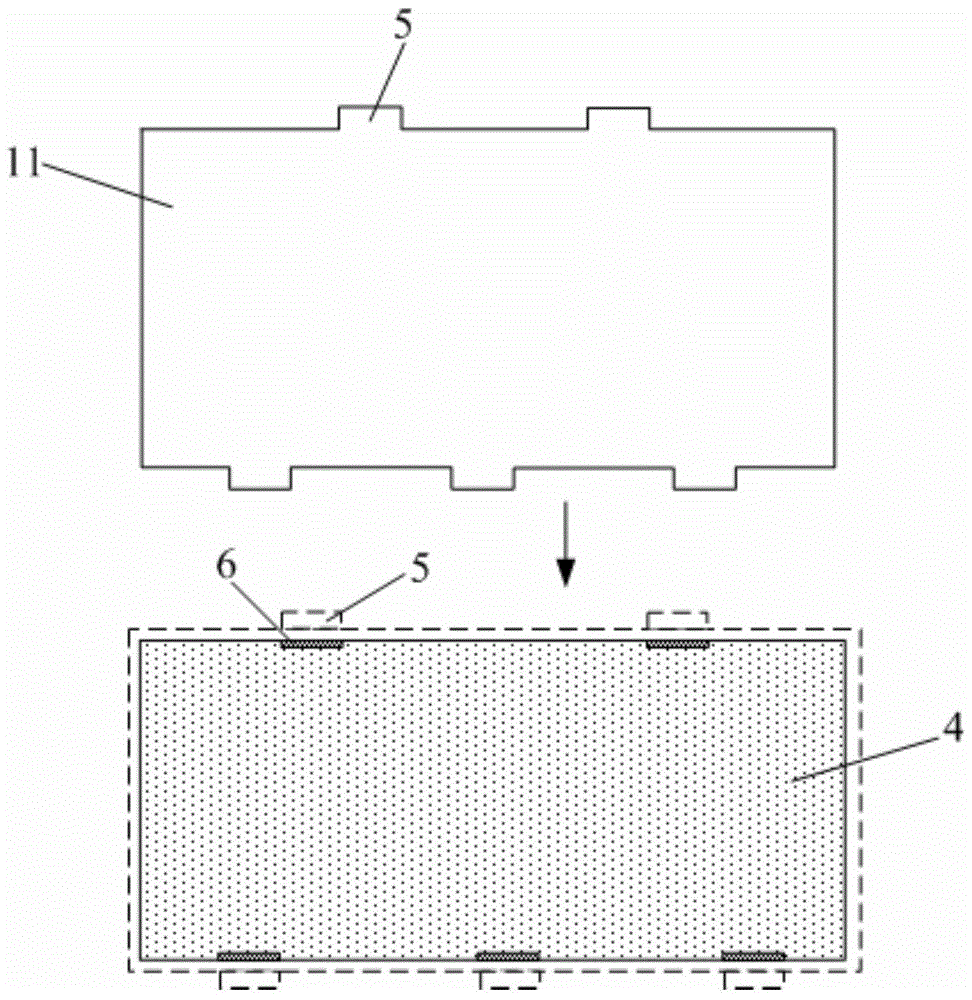
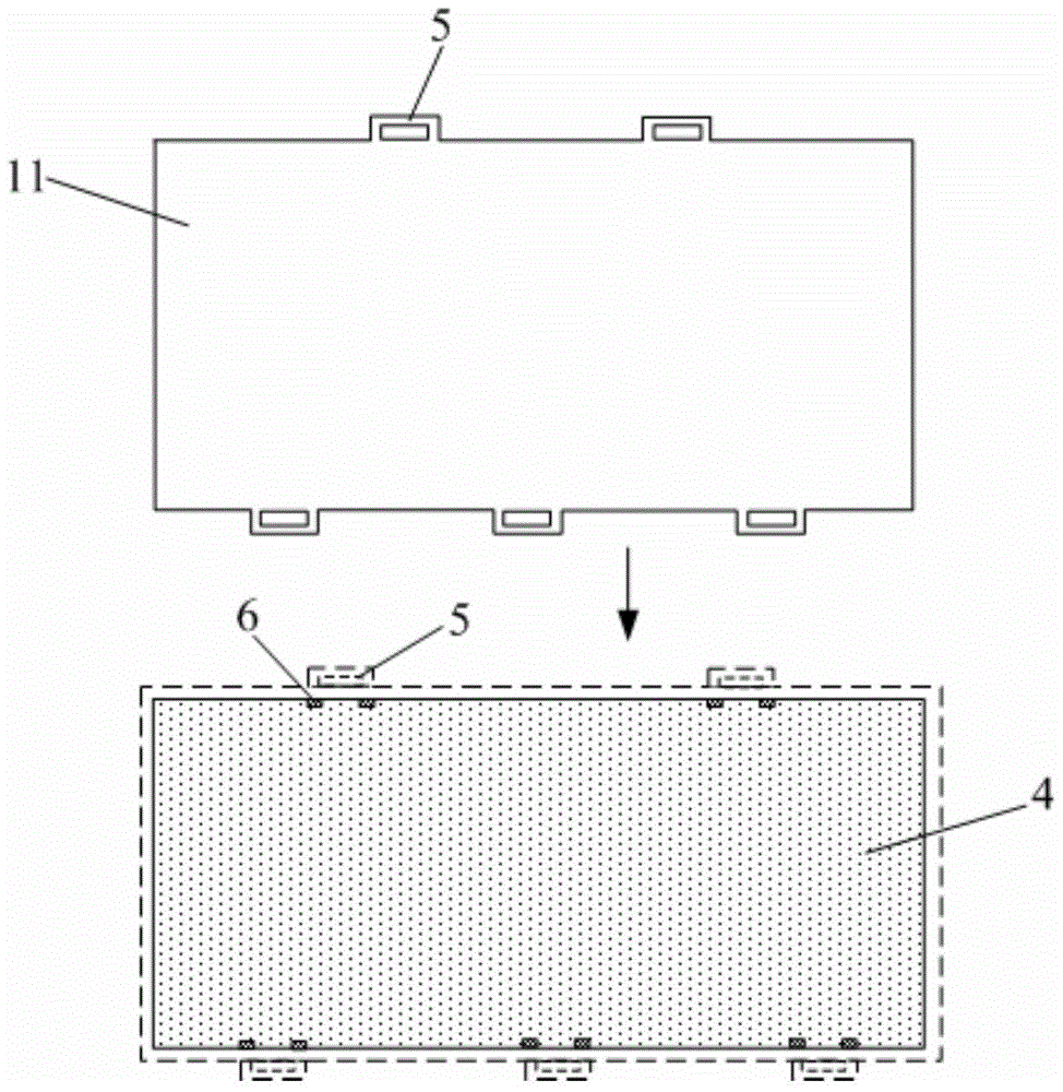
[0032] This embodiment provides a backlight, such as Figure 4 and Figure 5 As shown, it includes the light guide plate and the film material group 1 arranged above the light guide plate. The light emitted by the backlight passes through the light guide plate and the film material group 1 in sequence and then is emitted. The partial edge of the film material group 1 extends outward to form a fixed structure 2 The film material set 1 includes a prism sheet 11, and a diffusion layer 3 is provided on the light exit surface of the fixed structure 2 of the prism sheet 11, and the diffusion layer 3 is used to make the light emitted from the light exit surface of the fixed structure 2 uniform.

[0033] Wherein, the fixing structure 2 is used to fix the film material group 1 in the backlight source. The setting of the diffusion layer 3 on the light-emitting surface of the fixed structure 2 can make the backlight light emitted from the light-emitting surface of the fixed structure 2 ...

Embodiment 2

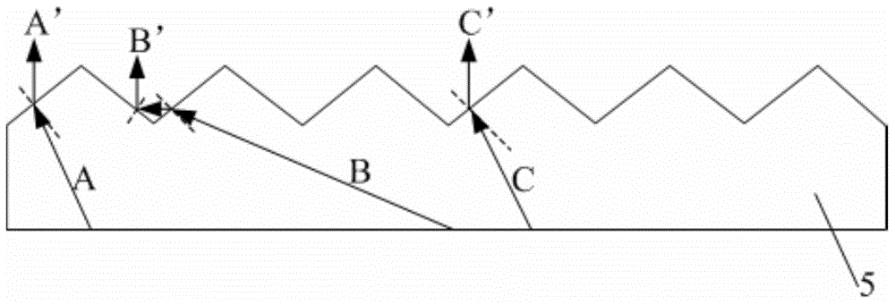
[0042] This embodiment provides a backlight source. The difference from Embodiment 1 is that Figure 7 As shown, the diffusion layer 3 is made of quantum dot material. Quantum dots have a particle size in the range of 1-10 nm.

[0043] Quantum dots within this particle size range can be excited by the blue part of the white light emitted by the backlight. On the one hand, this can increase the brightness of the light emitted from the light-emitting surface of the fixed structure 2 after passing through the diffusion layer 3. On the other hand, the white light After the quantum dot material is excited by the blue part in the figure, since the quantum dot material is nanoscale, it will diffract the light passing through the diffusion layer 3, so that the irradiation direction of the light passing through the diffusion layer 3 is randomly distributed, thereby improving the fixed structure The brightness difference between the edge of the visible area corresponding to 2 and other...

Embodiment 3

[0046] This embodiment provides a display panel, including the backlight source in any one of Embodiments 1-2.

[0047] By adopting the backlight source in any one of the embodiments 1-2, the shadow appearing on the edge of the visible area of ​​the corresponding fixed structure of the display panel is eliminated, thereby improving the display effect of the display panel.


PUM

PropertyMeasurementUnit
particle diameteraaaaaaaaaa

Abstract

The invention provides a backlight source, a display panel and a display device. The backlight source comprises a light guide plate, and a membrane material group arranged above the light guide plate, wherein rays of light emitted by the backlight source pass through the light guide plate and the membrane material group and then are irradiated; the local edge of the membrane material group extends outwards to form a fixed structure; the membrane material group comprises a prismatic lens; a diffusion layer is arranged on the outgoing surface of the fixed structure of the prismatic lens and used for homogenizing the rays of light emitted by the outgoing surface of the fixed structure. As the diffusion layer is arranged on the outgoing surface of the fixed structure, the backlight source can enable the backlight rays, which are irradiated by the outgoing surface of the fixed structure, to be homogenized, so as to eliminate the shadow at the edge of the visible area (namely the backlight area which cannot be shielded by a rubber frame and other packaging structures outside the rubber frame) corresponding to the fixed structure, and further improve the backlight effect of the backlight source.

Description

technical field [0001] The present invention relates to the technical field of liquid crystal display, in particular to a backlight source, a display panel and a display device. Background technique [0002] A liquid crystal display (LCD: Liquid Crystal Display) has become a mainstream product in flat panel displays due to its small size, low power consumption, and no radiation. [0003] A backlight is an essential component in an LCD display. A backlight usually consists of a backplane, a light source, a light guide plate, a film group, and a plastic frame. Wherein, the film material group includes a diffusion sheet and a prism sheet placed above the light guide plate. [0004] In order to well fix the film material group in the backlight source, lugs are usually formed on the edge of the film material group, and the lugs are formed simultaneously when cutting the film material sheets forming the film material group. Such as figure 1 As shown, the lug 5 is in the shape ...

Claims


Application Information

Patent Timeline
Patent Type & Authority Patents(China)
IPC IPC(8): G02F1/13357F21S8/00F21V13/12
CPCF21S2/005F21V5/02F21V13/12
Inventor 贾丽丽马青尹大根
Owner BOE TECH GRP CO LTD
Why Eureka
Try Eureka