Disconnecting switch shunting bridge
A technology of isolating switches and shunt bridges, applied in the direction of electric switches, air switch parts, high-voltage air circuit breakers, etc., to avoid the loss of power supply and reduce the degree of overheating
- Summary
- Abstract
- Description
- Claims
- Application Information
AI Technical Summary
Problems solved by technology
Method used
Image
Examples
Embodiment 1
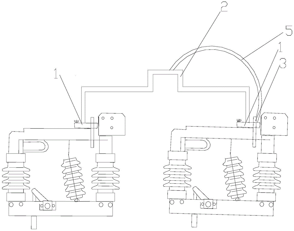
[0022] An isolating switch shunt bridge, such as figure 1 As shown, it includes: a bridge-shaped main body 2 and a control assembly; wherein, the two ends of the bridge-shaped main body 2 are provided with connectors connecting the contact fingers 1 of the isolating switch, the control assembly includes a temperature sensor and a push rod, and the sensing end of the temperature sensor is connected to the isolation switch. The contact 3 of the switch is connected, and the other end is connected with the push rod, and the push rod is connected with the bridge-shaped main body 2 to push the bridge-shaped main body 2 to move. The bridge-shaped main body 2 can form a bridge on the two isolating switch contacts 3 to realize effective shunting. In order to track the temperature rise of the isolating switch contact 3 more automatically and intelligently, a temperature sensor is used for temperature collection, and the high-temperature driving push rod is skillfully moved, and the driv...
Embodiment 2
[0029] This embodiment 2 is slightly modified on the basis of embodiment 1:
[0030] The connecting piece in embodiment 1 is modified as follows: two connecting arms, one connecting arm is hinged at both ends of the bridge-shaped main body 2, and the connecting arm overlaps with the contact finger 1 of the isolating switch. The connecting arm can be connected to the bridge body 2
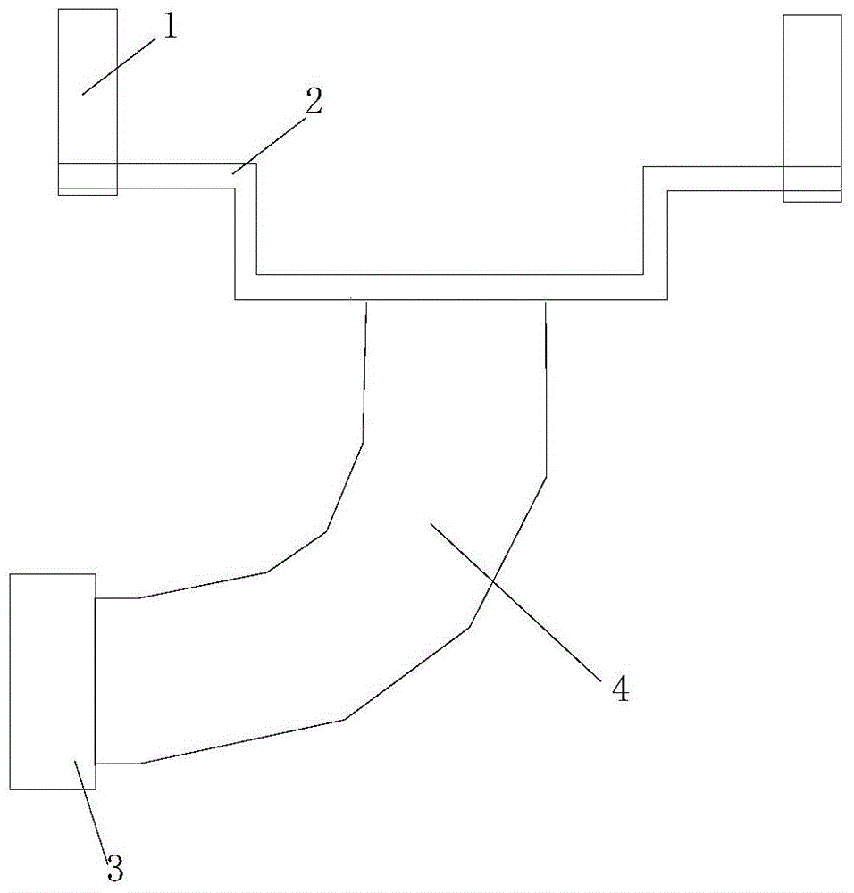
[0031] Such as figure 2 As shown, the temperature sensor in Embodiment 1 is modified to: a gas expander 4, one end of the gas expander 4 is provided with a temperature-sensing contact 3, and the temperature-sensing contact 3 extends to the inside of the gas expander 5, and the gas expander 4 Contains gas that expands when heated and contracts when cooled.
Embodiment 3
[0033] Present embodiment 3 carries out slight modification on the basis of embodiment 1:
[0034] The control assembly also includes: a processor and a driving motor; the sensing end of the temperature sensor is in contact with the contact of the isolating switch, the signal output end is connected with the signal input end of the processor, the processor is connected with the driving motor, and the output rod of the driving motor for the push rod. After the temperature sensor senses the temperature, it will transmit the temperature value to the processor. The processor processes the data and sends a driving signal to the drive motor. The output rod of the drive motor drives the push rod to push the bridge-shaped main body to move.
[0035] The present invention analyzes the existing equipment, and the large current-carrying capacity is the main reason causing the heating of the isolating switch contacts. The developed isolating switch shunt bridge can reduce the carrying cap...
PUM
 Abstract
Description
Claims
Application Information
 - R&D
- Intellectual Property
- Life Sciences
- Materials
- Tech Scout
- Unparalleled Data Quality
- Higher Quality Content
- 60% Fewer Hallucinations
Browse by: Latest US Patents, China's latest patents, Technical Efficacy Thesaurus, Application Domain, Technology Topic, Popular Technical Reports.
© 2025 PatSnap. All rights reserved.Legal|Privacy policy|Modern Slavery Act Transparency Statement|Sitemap|About US| Contact US: help@patsnap.com


