
A balun combiner integrated feed network

A feeding network and impedance matching technology, which is applied in the field of feeding network, can solve the problems that the low-noise amplifier phase consistency cannot be guaranteed, the insertion loss and impedance mismatch will deteriorate, and the performance of the feed source network will deteriorate, and the structure will be simple , Small insertion loss, low transmission loss

Active Publication Date: 2017-04-05
NO 54 INST OF CHINA ELECTRONICS SCI & TECH GRP
View PDF4 Cites 0 Cited by
  • Summary
  • Abstract
  • Description
  • Claims
  • Application Information

AI Technical Summary

Problems solved by technology

[0004] 2. The Chinese patent number is CN103151602, and the title is "Broadband Multi-Dipole Antenna with Frequency-Independent Radiation Characteristics". The patent also discloses a feed network, a feed network in the form of an active balun. The electrical network requires a specially designed precision process for manufacturing, and the cost is very high, and it contains 4 low-noise amplifiers, and the phase consistency of the low-noise amplifier cannot be guaranteed
[0005] 3. The Chinese patent number is CN103151602, titled "Broadband Multi-Dipole Antenna with Frequency-Independent Radiation Characteristics", which discloses a feed network, a feed network in the form of 4 passive baluns, this The feed network can only be 3GHz to 13.5GHz. If the frequency multiplier is higher, the insertion loss and impedance mismatch will deteriorate sharply, resulting in poor performance of the entire feed network.
[0006] 4. Feed network in the form of double-layer parallel passive balun. This kind of feed network places two layers of balun in a small space (1 ~ 2mm), and it is difficult to realize the process.
In addition, when the frequency is above 9GHz, it will have a great impact on the standing wave, and the overall performance of the feed network will deteriorate

Method used


Image

  • A balun combiner integrated feed network
  • A balun combiner integrated feed network
  • A balun combiner integrated feed network

Examples


Embodiment Construction

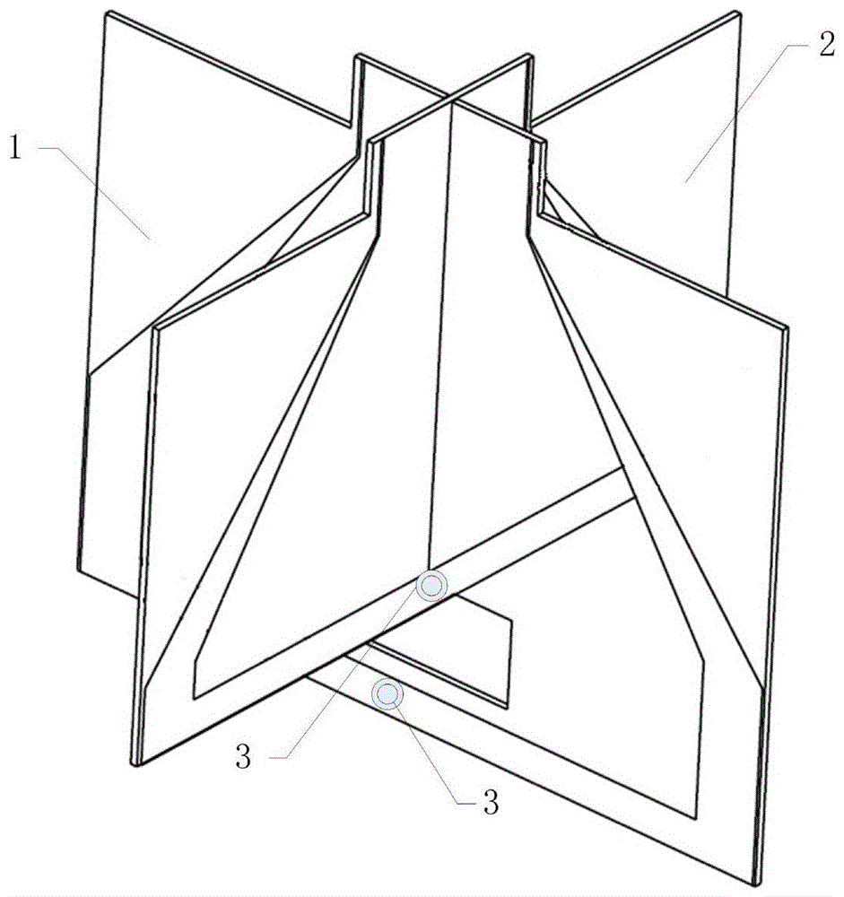
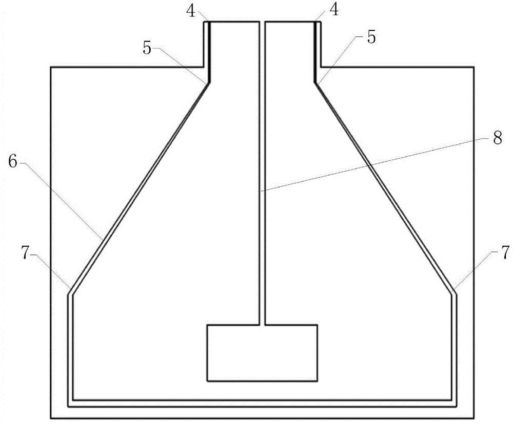
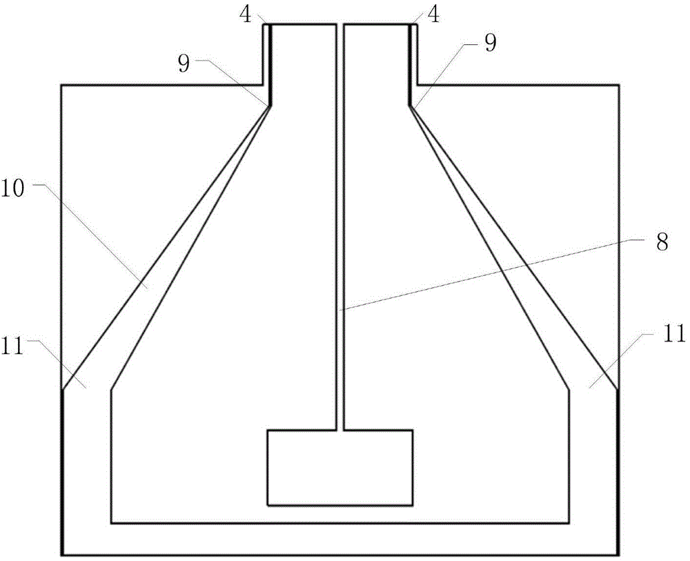
[0024] Below, combine Figure 1 to Figure 5 The present invention is further described.

[0025] A balun combiner integrated feed network of the present invention includes a first impedance matching printed board 1 and a second impedance matching printed board 2 . The front of the first impedance matching printed board is provided with two tapered metal microstrip lines 6, and the narrow ends 5 of the two metal microstrip lines are respectively provided with an antenna interface 4, and the two metal microstrip lines are provided with an antenna interface 4. The wide ends 7 are respectively connected to the inner conductors of the coaxial port 3; two tapered metal microstrip ground wires 10 are arranged on the back of the impedance matching printed board, and each of the narrow ends 9 of the two metal microstrip ground wires is provided with a The antenna interface 4, the wide ends 11 of the two metal microstrip ground wires are connected to the outer conductor of the coaxial ...


PUM


Abstract

The invention discloses a balun combiner integrated feed network in the field of wireless communication and radio astronomy, which includes a first impedance matching printed board, and is characterized in that: the front of the impedance matching printed board is provided with Two tapered metal microstrip lines, the narrow ends of the two metal microstrip lines are respectively provided with an antenna interface, and the wide ends of the two metal microstrip lines are respectively connected to the inner conductor of the coaxial port; the impedance matching printed board There are two gradually changing metal microstrip ground wires on the back of the board, each of the narrow ends of the two metal microstrip ground wires is provided with an antenna interface, and the wide ends of the two metal microstrip ground wires are respectively connected to the outer conductor of the coaxial port. connected. The invention has the advantages of impedance transformation, balanced-unbalanced port conversion, port synthesis, low loss, high feed efficiency, compact structure, low processing cost, etc., and is especially suitable for working in broadband dual-line polarization or dual circular polarization The feed network of the antenna in the application case.

Description

technical field [0001] The invention relates to a feed network of a broadband reflector antenna in the technical fields of communication, broadband direction finding, telemetry, remote sensing, radio astronomy, etc., and is specifically a feed network integrated with a balun combiner. Background technique [0002] At present, the feed network used in the broadband reflector antenna has the following forms. Although they have their own characteristics in performance, they all have some shortcomings. [0003] 1. The Chinese patent number is CN103151602, titled "Broadband Multi-Dipole Antenna with Frequency-Independent Radiation Characteristics", which discloses a feed network, 8 baluns and 8 low-noise amplifiers in the form of feeds Network, this kind of feeding network structure is complex, the cost of using 8 low-noise amplifiers is high, the phase consistency cannot be guaranteed, and the broadband 180° phase shifter has a large loss. (As shown in Figure 8 of the accompany...

Claims


Application Information

Patent Timeline
Patent Type & Authority Patents(China)
IPC IPC(8): H01Q5/50
Inventor 孙良牛传峰刘超耿京朝赵东贺杨国栋马万垒张廷恒卢飞宇
Owner NO 54 INST OF CHINA ELECTRONICS SCI & TECH GRP
Learn More