Method of producing a syringe barrel for medical purposes and device for carrying out said method

A technology for a syringe barrel and a delivery device, which is applied in the directions of syringes, hypodermic injection devices, and other medical devices, can solve problems such as expensive

Active Publication Date: 2015-03-25
SCHOTTLI
View PDF11 Cites 3 Cited by
  • Summary
  • Abstract
  • Description
  • Claims
  • Application Information

AI Technical Summary

Problems solved by technology

It is very expensive to manufacture such syringe barrels with needles

Method used


Image

  • Method of producing a syringe barrel for medical purposes and device for carrying out said method
  • Method of producing a syringe barrel for medical purposes and device for carrying out said method
  • Method of producing a syringe barrel for medical purposes and device for carrying out said method

Examples


Embodiment Construction

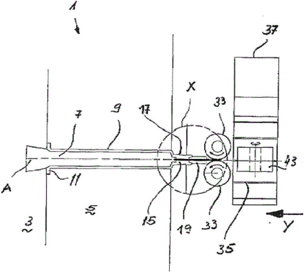
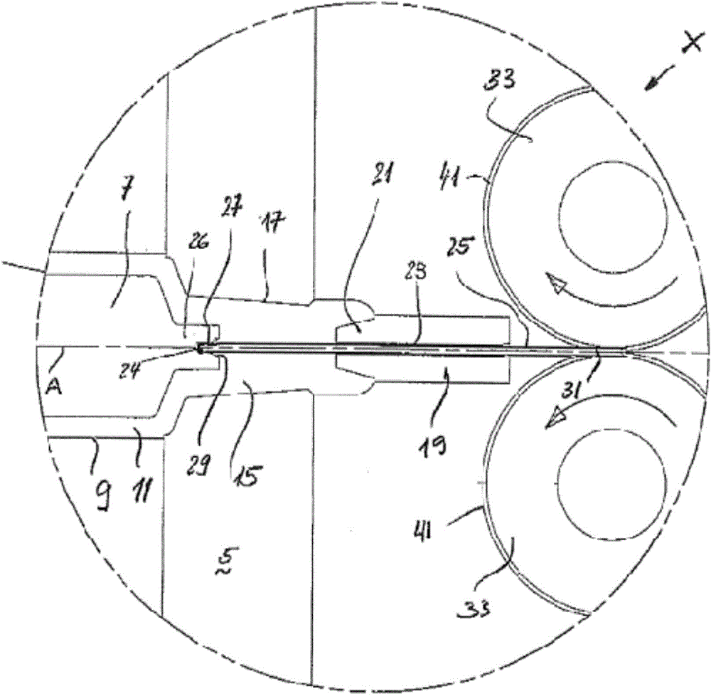
[0012] Reference number 3 shows the movable parts of the injection mold 1 in a schematic diagram, and reference number 5 shows the fixed parts of the injection mold 1 . On the movable part 3 of the injection mold 1 a core 7 is fixed, while the core 7 is inserted into the cavity 9 of the syringe barrel 11 in the fixed mold part 5 . Next, it can be seen in the figure on the right, for example, that next to the cylindrical cavity 9 there is a conical cavity portion 17 formed by the collection needle 15 . Extending in the needle guide tube 19 at the end of the hollow portion 17 is a conical blunt end 21 . An axial bore 23 in the guide tube 19 exhibits a diameter into which the rear end tail 24 of the needle 25 can be inserted substantially without play and sealingly when spraying.

[0013] The free end 26 of the core 7 forms a blind bore 27 which essentially comprises a conical inlet region 29 at the input.

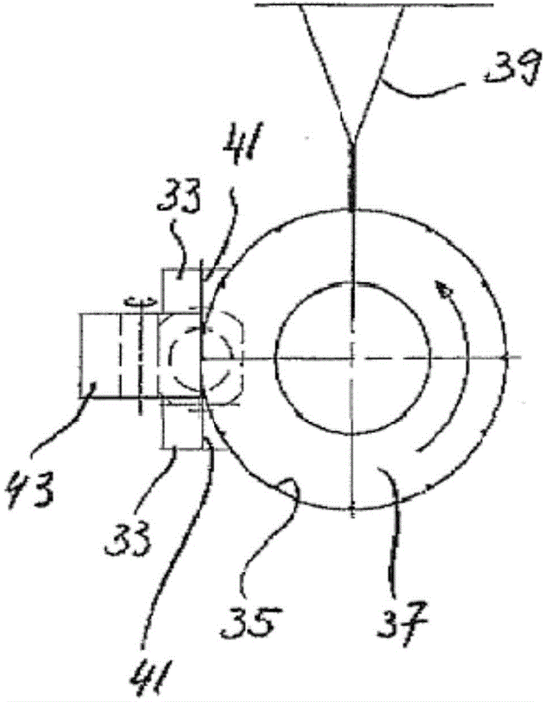
[0014] The needle 25 with the tip fitted at the front end 31 is held b...


PUM


Abstract

Syringe barrels (11) are fitted with hypodermic needles (25) before the plastic is injected. For this purpose, the hypodermic needles (25) are introduced through the stationary part (5) of the injection mold (1) by a suitable transport device (transport rollers (33)).

Description

technical field [0001] The invention relates to a method of making a syringe barrel according to the general designation in claim 1 . [0002] The invention also relates to a device for carrying out the method according to the general designation in claim 5 . Background technique [0003] Syringes for medical use consist of an injection barrel with a needle mounted on the front end, and a plunger that draws the injection medium at one end and then injects it. In most cases, the needle is packaged and shipped separately from the syringe or syringe barrel and plunger. But it is well known that needles are installed in syringes, especially for the production of vaccines. In the production of such syringes, the mold is opened using a handling device, a sharp-pointed needle is inserted into the cavity of the injection mold, and is then partially sealed by the plastic liquid during the injection process. Using an open mold to mount the needle, the needle must be machined in suc...

Claims


Application Information

Patent Timeline
Patent Type & Authority Applications(China)
IPC IPC(8): A61M5/34A61M5/31B29C45/00B29C45/03B29C45/14B29C45/26B29C45/40
CPCB29C45/14008A61M5/343A61M2207/00A61M2207/10B29C45/14065B29C45/14262B29C45/14336B29C45/14598B29C45/261B29C2045/14131B29C2045/14139B29L2031/7544
Inventor 洛塔尔·扎恩
Owner SCHOTTLI
Why Eureka
Try Eureka