High precision displacement servo thin parts assembly guide groove

A technology of parts assembly and guide grooves, applied in metal processing, metal processing equipment, manufacturing tools, etc., can solve the problems of axial offset, difficult automatic assembly, expensive production costs, etc., and achieve the effect of precise axial guidance

Inactive Publication Date: 2017-05-10
SHANGHAI UNIV
View PDF6 Cites 0 Cited by
  • Summary
  • Abstract
  • Description
  • Claims
  • Application Information

AI Technical Summary

Problems solved by technology

[0002] Due to its unique mechanical structure, the axial dimension of thin parts is very small, usually below 0.2mm. In order to ensure better precision at this scale, high-precision machining equipment is required. would incur expensive production costs
Many small and medium-sized machining manufacturers in China can only achieve a machining accuracy of 0.01mm, so the same batch of thin parts produced must have a tolerance of ±0.01mm. Autowiring is difficult due to size changes
The size of the traditional guide groove is fixed. When the axial dimension of the thin part is smaller than the height of the groove, there will be a large gap between the thin part and the guide groove, which will cause the thin part to shift and change direction in the axial direction when moving in the groove , can not realize the real guide; on the contrary, the thin part is in too tight contact with the guide groove, and the extrusion force is too large, so that the thin part cannot move in the guide groove
Therefore, at present, the assembly of such thin parts is manually operated, using special fixtures, and manually assembled, which consumes a lot of manpower

Method used


Image

  • High precision displacement servo thin parts assembly guide groove
  • High precision displacement servo thin parts assembly guide groove
  • High precision displacement servo thin parts assembly guide groove

Examples


Embodiment Construction

[0019] The specific embodiments of the present invention will be further described below in conjunction with the accompanying drawings.

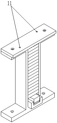
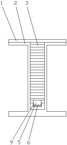
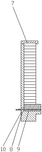
[0020] Such as Figure 1~Figure 5 The specific structure of a high-precision displacement servo thin part assembly guide groove shown is:

[0021] A high-precision displacement servo thin-shaped parts assembly guide groove, including a cover plate 1, a frame body 2, a laminated piezoelectric ceramic 3, a guide groove 9, an indenter 5, and a strain sensor 6; the cover plate 1 and The frame body 2 is connected to the bottom plate; one end of the laminated piezoelectric ceramic 3 is pasted in the positioning groove 7 at the bottom of the cover plate 1, and the other end is pasted with an indenter 5, and the bottom of the indenter 5 is connected to a strain gauge force sensor 6; The bottom of the frame body 2 is provided with a guide groove 9 .

[0022] The frame body 2 is closed on three sides and is used to limit the position of the laminate...


PUM


Abstract

The invention relates to a high-precision displacement servo thin part assembly guide groove. The high-precision displacement servo thin part assembly guide groove comprises a cover plate, a frame body, laminated piezoelectric ceramic, a guide groove, a press head and a strain gauge force sensor, wherein the cover plate is connected with an upper bottom plate of the frame body; one end of the laminated piezoelectric ceramic is adhered in a positioning groove in the bottom of the cover plate, and the other end of the laminated piezoelectric ceramic is adhered to the press head; the bottom of the press head is connected with the strain gauge force sensor; the guide groove is formed in the bottom of the frame body. According to the high-precision displacement servo thin part assembly guide groove, axial deviation and deformation of a thin part in the guide groove can be effectively limited, and accurate axial guide of the thin part in the guide groove is realized.

Description

technical field [0001] The invention relates to a precision mechanical assembly device, in particular to a high-precision displacement servo thin part assembly guide groove. Background technique [0002] Due to its unique mechanical structure, the axial dimension of thin parts is very small, usually below 0.2mm. In order to ensure better precision at this scale, high-precision machining equipment is required. Expensive production costs are incurred. Many small and medium-sized machining manufacturers in China can only achieve a machining accuracy of 0.01mm, so the same batch of thin parts produced must have a tolerance of ±0.01mm. Autowiring is made difficult by changes in size. The size of the traditional guide groove is fixed. When the axial dimension of the thin part is smaller than the height of the groove, there will be a large gap between the thin part and the guide groove, which will cause the thin part to shift and change direction in the axial direction when movin...

Claims


Application Information

Patent Timeline
Patent Type & Authority Patents(China)
IPC IPC(8): B23P19/00
CPCB23P19/001B23P19/105
Inventor 李政陆利新赵岩陈荣莲
Owner SHANGHAI UNIV
Why Eureka
Try Eureka