Electromagnet with buffer structure

A buffer structure and electromagnet technology, applied in the field of electromagnets, can solve the problems of large electromagnet volume, large current, and unfavorable product miniaturization

Active Publication Date: 2015-04-01
CHANGSHU SWITCHGEAR MFG CO LTD (FORMER CHANGSHU SWITCHGEAR PLANT)
View PDF5 Cites 4 Cited by
  • Summary
  • Abstract
  • Description
  • Claims
  • Application Information

AI Technical Summary

Problems solved by technology

The consequences of this are: 1. Excessive driving current produces high power consumption, especially when driving at low voltage, the current is particularly large; 2. The electromagnet is too large, which is not conducive to product miniaturization

Method used


Image

  • Electromagnet with buffer structure
  • Electromagnet with buffer structure
  • Electromagnet with buffer structure

Examples


Embodiment

[0017] Example: see Figure 2-5 Shown:

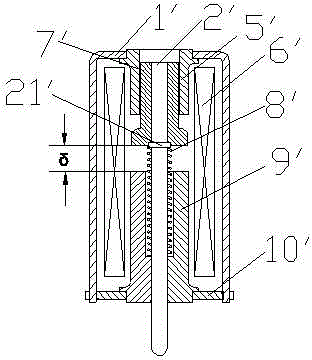
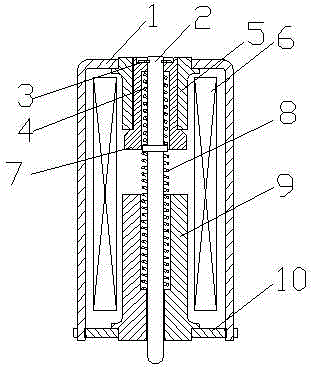
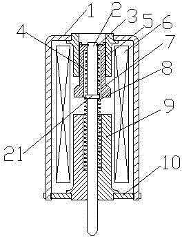
[0018] An electromagnet with a buffer structure, including a yoke, a push rod 2, a coil 6, a moving end magnetic pole 7, a return spring 8, and a static end magnetic pole 9;

[0019] The yoke includes an intermediate yoke 1 , a moving yoke 5 and a stationary yoke 10 . The magnetic yoke forms a hollow cavity with openings on both sides. A pair of moving end yokes 5 are symmetrically fixed on the left and right sides of the opening of the upper end of the cavity formed by the middle yoke 1, and the static end magnetic poles 9 and a pair of static end yokes 10 are fixed and symmetrically located in the middle magnetic yoke. On the left and right sides of the lower part of the cavity of the yoke 1 , the coil 6 is arranged in the hollow cavity formed by the yoke, and surrounds the static end magnetic pole 9 and the outer side of the moving end yoke 5 . The moving end magnetic pole 7 is arranged in the center hole of the moving end yoke 5 ...


PUM


Abstract

The invention relates to an electromagnet with a buffer structure. The electromagnet comprises a magnetic yoke, a static end magnetic pole, a coil, a jacking rod and a movable end magnetic pole, wherein the movable end magnetic pole is glidingly arranged in a center hole of the movable end magnetic yoke, one end, facing the static end magnetic pole, of the jacking rod extends through the center hole of the static end magnetic pole and then extends out to be used as a thrust output end, and in addition, a reset spring acts between the jacking rod and the static end magnetic pole. The electromagnet is characterized in that one end, facing the movable end magnetic yoke, of the jacking rod extends to pass through the inner hole of the movable end magnetic pole, a buffer spring also acts between the jacking rod and the movable end magnetic pole, and the jacking rod moves towards the static end magnetic pole side relative to the movable end magnetic pole through the elasticity of the buffer spring, so that a blocking part is matched with the movable end magnetic pole. The electromagnet has the advantages that under the condition of the same requirements, the rigidity requirement on the electromagnet per se is relatively reduced, the miniaturization of the electromagnet is favorably realized, in addition, the driving current is small, and the energy is saved.

Description

technical field [0001] The invention relates to an electromagnet, in particular to an electromagnet with a buffer structure. Background technique [0002] At present, there are existing electromagnets, and the representative structures are as follows: figure 1 As shown, including the middle yoke 1', the ejector rod 2', the moving end yoke 5', the coil 6', the moving end magnetic pole 7', the return spring 8', the static end magnetic pole 9' and the static end yoke 10', The intermediate yoke 1 ′, the moving yoke 5 ′, and the static yoke 10 ′ are collectively referred to as yokes. The upper opening of the cavity formed by the intermediate yoke 1' is fixed with a moving end yoke 5', and the static end magnetic pole 9' is fixed with the static end yoke 10' and is located in the cavity of the intermediate yoke 1' In the lower part, the coil 6' is sleeved on the outside of the static end magnetic pole 9' and the moving end yoke 5', the coil 6' is located inside the middle yoke 1...

Claims


Application Information

Patent Timeline
Patent Type & Authority Applications(China)
IPC IPC(8): H01F7/08H01F7/121
Inventor 毛振风俞晓峰周敏琛
Owner CHANGSHU SWITCHGEAR MFG CO LTD (FORMER CHANGSHU SWITCHGEAR PLANT)
Why Eureka
Try Eureka