Multistage gas gun anti-recoil device

An anti-recoil and air cannon technology, applied in the direction of compressed air guns, weapons without explosives, weapon types, etc., can solve the problems of high impact strength of the cannon body, achieve the effect of reducing the bearing strength of the foundation, reducing the rigidity requirements, and simple structure

Active Publication Date: 2019-06-07
SHANXI NORTH MACHINE BUILDING
View PDF6 Cites 2 Cited by
  • Summary
  • Abstract
  • Description
  • Claims
  • Application Information

AI Technical Summary

Problems solved by technology

[0003] The purpose of the present invention is to overcome the defects of the prior art, in order to solve the problem that various reaction forces have a large impact on the cannon body during the launching process of the existing multi-stage air cannon projectile, and propose a multi-stage air cannon anti-recoil device

Method used


Image

  • Multistage gas gun anti-recoil device
  • Multistage gas gun anti-recoil device
  • Multistage gas gun anti-recoil device

Examples


Embodiment 1

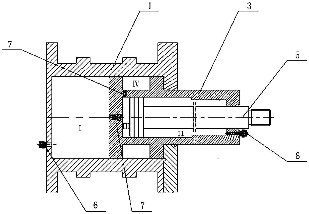
[0014] Such as figure 1 As shown, a multi-stage gas cannon anti-recoil device includes: cylinder body I1, cylinder body II3, buffer rod 5, gas injection valve 6, balance valve 7;

[0015] Cylinder Ⅰ1 is fixedly connected with the gun body, as the retention basis of the whole device, there is no relative movement with the gun body during the firing process of the gas cannon; cylinder Ⅱ3 is fixedly installed on the cylinder Ⅰ1, and the cylinder Ⅰ1 is divided into two airtight chambers One end of the buffer rod 5 is movably connected with the cylinder body II3, and the cylinder body II3 is divided into two airtight chambers; Pressure gas, each chamber is connected through the balance valve, and the pressure of each chamber is adjusted through the balance valve 7 at different stages during the firing process of the gas cannon, so as to realize the buffering of recoil and forward momentum.

Embodiment 2

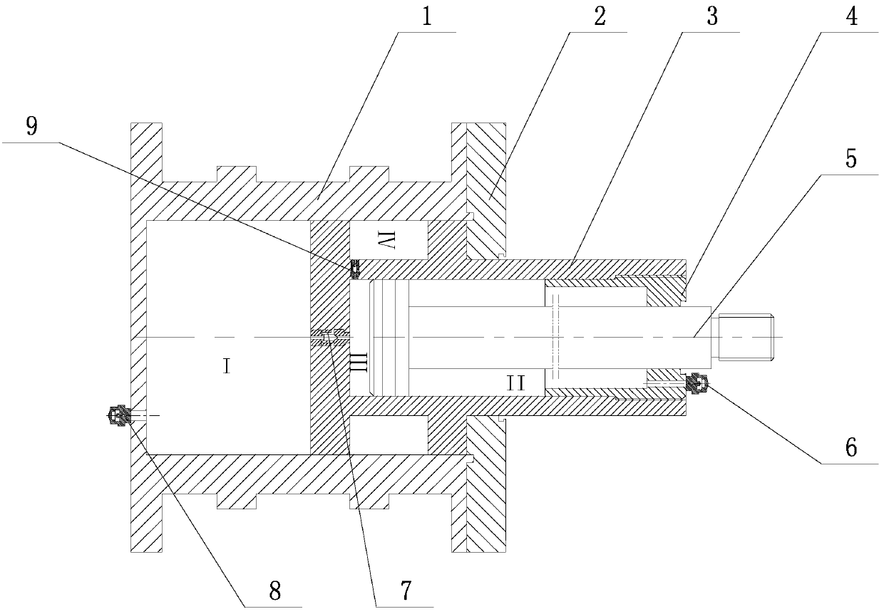
[0017] Such as figure 2 As shown, a multi-stage air cannon anti-recoil device consists of cylinder body I1, cover plate 2, cylinder body II3, fixed seat 4, buffer rod 5, gas injection valve 6, balance valve 7, gas injection valve I8, balance valve Ⅰ9 composition;

[0018] (1) Cylinder block I1 is connected to the gun body (specifically, the barrel of the gas gun), and there is no relative movement with the gun body during the firing of the gas gun;

[0019] (2) The cover plate 2 is used as the connecting cover plate after the assembly of the cylinder body I1 and the cylinder body II3, so that a closed gas chamber is formed between the cylinder body I1 and the cylinder body II3; here, between the cover plate 2 and the cylinder body I1 It can be a separate structure, connected by a sealed connection, or an integrated structure connected by welding, or other structures thought of by those skilled in the art;

[0020] (3) Cylinder body II3, used to connect cylinder body I1 and ...


PUM


Abstract

The invention relates to a multistage gas gun anti-recoil device and belongs to the technical field of mechanical machining. The multistage gas gun anti-recoil device comprises a cylinder block I (1),a cylinder block II (3), a buffer rod (5), a gas injection valve (6) and a balance valve (7). The cylinder block I is fixedly connected with a gun piece. The cylinder block II is fixedly connected tothe cylinder block I. One end of the buffer rod is movably connected with the cylinder block II. One end of the buffer rod is connected with the gun piece. Cavities of the cylinder block I and the cylinder block II are filled up with gas at different pressures through the gas injection valve. The cavities communicate through the balance valve. At different stages of the gas gun shooting process,the pressures of the cavities are adjusted through the balance valve to implement buffering on recoil force and forward impact force. Compared with the prior art, the multistage gas gun anti-recoil device can accurately return zero to shifting generated under different working conditions within short time in the gas gun shooting process, gently absorb peak stress generated in different stress directions and reduce the requirements for rigidity and strength and the foundation load bearing strength, is simple in structure and achieves the combined operation effect of multiple recoil mechanisms and counter-recoil mechanisms of an original gas gun.

Description

technical field [0001] The invention relates to a multi-stage gas cannon anti-recoil device, which belongs to the technical field of gas cannon anti-recoil devices. Background technique [0002] The recoil force and forward momentum generated by the gas guns of two or more levels (abbreviated as multi-stage gas guns) during the firing process are too large to cause damage to the gun body itself and the foundation. The existing anti-recoil structure uses a combination of multiple parking machines and re-entry machines to reduce the impact force of the recoil. The structure is complex, and the anti-recoil resistance is adjusted through fluid holes of different sizes. The buffer function fails, destroying the gun body and foundation. The forward momentum that occurs at different stages of the firing process can only be absorbed by the gun body, which affects the rigidity of the gun body. Contents of the invention [0003] The purpose of the present invention is to overcome t...

Claims


Application Information

Patent Timeline
Patent Type & Authority Applications(China)
IPC IPC(8): F41B11/00
Inventor 李保在李计明刘洁霍志刚解军昌郝春阳杨博李赟李燕伟王海维
Owner SHANXI NORTH MACHINE BUILDING
Why Eureka
Try Eureka