

Rebar arrangement method of buildings
A technology for steel bar layout and building, which is applied in the direction of buildings, building components, building reinforcements, etc., can solve the problems of house stability and firmness danger, foundation load, etc., to improve firmness and stability, reduce construction costs, and load-bearing powerful effect
- Summary
- Abstract
- Description
- Claims
- Application Information
AI Technical Summary
Problems solved by technology
Method used
Image


Examples
Embodiment 1
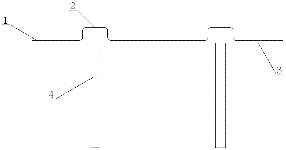
[0030] see Figures 1 to 2 Shown, a kind of reinforcing bar arrangement method of building construction adopts the mode of bow-shaped arrangement of reinforcing bars, and described method comprises the following steps:
[0031] (1) Build the pouring formwork 3, the top surface of the formwork 3 is flush with the top surface of the load-bearing member 4;
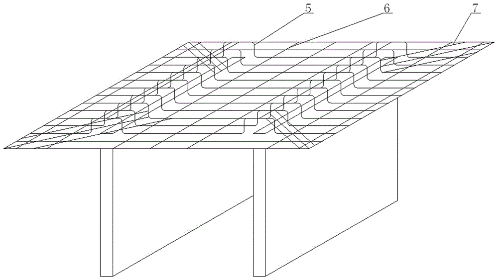
[0032] (2) Arrangement of steel bars, pre-place several positioning ribs 6 on the top surface of the load-bearing member, where the number of positioning ribs 6 is determined according to the distance between the two load-bearing members 4; On the pre-placed positioning ribs 6, the positioning ribs 6 are fixed on the main force ribs 5, and the distance between the main force ribs 5 is 8cm; the positioning ribs 6 are arranged, and the positioning ribs 6 are placed on the main force ribs 5. When the load-bearing member is 4, the arrangement is omitted, and the positioning ribs 6 are connected and fixed to the main ribs 5, and ...
Embodiment 2
[0040] see Figures 1 to 2 Shown, a kind of reinforcing bar arrangement method of building construction adopts the mode of bow-shaped arrangement of reinforcing bars, and described method comprises the following steps:
[0041] (1) Build the pouring formwork 3, the top surface of the formwork 3 is flush with the top surface of the load-bearing member 4;
[0042] (2) Arrangement of steel bars, pre-place several positioning ribs 6 on the top surface of the load-bearing member, where the number of positioning ribs 6 is determined according to the distance between the two load-bearing members 4; On the pre-placed positioning ribs 6, the positioning ribs 6 are fixed on the main force ribs 5, and the distance between the main force ribs 5 is 10cm; the positioning ribs 6 are arranged, and the positioning ribs 6 are placed on the main force ribs 5. When the load-bearing member is 4, the layout is omitted, and the positioning rib 6 is connected to the fixed main rib 5, and the distanc...
Embodiment 3
[0050] see Figures 1 to 2 Shown, a kind of reinforcing bar arrangement method of building construction adopts the mode of bow-shaped arrangement of reinforcing bars, and described method comprises the following steps:
[0051] (1) Build the pouring formwork 3, the top surface of the formwork 3 is flush with the top surface of the load-bearing member 4;
[0052] (2) Arrangement of steel bars, pre-place several positioning ribs 6 on the top surface of the load-bearing member, where the number of positioning ribs 6 is determined according to the distance between the two load-bearing members 4; On the pre-placed positioning ribs 6, the positioning ribs 6 are fixed on the main force ribs 5, and the distance between the main force ribs 5 is 12cm; the positioning ribs 6 are arranged, and the positioning ribs 6 are placed on the main force ribs 5. When the load-bearing member is 4, the arrangement is omitted, and the positioning ribs 6 are connected to the fixed main ribs 5, and the d...
PUM
 Abstract
Description
Claims
Application Information