A Method for Suppressing Power Swing Peak of UHV Tie Line Based on DC Emergency Control

A tie-line power and emergency control technology, applied in the direction of reducing/preventing power oscillation, etc., can solve the problems of unable to complete large power modulation in a short time, unable to adapt to different scales of transient disturbance power impact, etc., to achieve the improvement of transient power The effect of angular stability

Inactive Publication Date: 2017-07-07
HUAZHONG UNIV OF SCI & TECH +2
View PDF2 Cites 2 Cited by
  • Summary
  • Abstract
  • Description
  • Claims
  • Application Information

AI Technical Summary

Problems solved by technology

[0010] In view of the above defects or improvement needs of the prior art, the present invention provides a method for suppressing the peak power swing of the tie line, which measures the power swing of the tie line in real time, and calculates the starting and exiting criteria and the DC emergency power modulation amount. Obtain the output control decision and act on the emergency power control unit of the designated DC system, so as to realize the suppression of the power swing peak of the tie line, and solve the problem that the current control method cannot complete a large power modulation in a short time or cannot adapt to transient disturbances of different scales The problem with power shocks

Method used


Image

  • A Method for Suppressing Power Swing Peak of UHV Tie Line Based on DC Emergency Control
  • A Method for Suppressing Power Swing Peak of UHV Tie Line Based on DC Emergency Control
  • A Method for Suppressing Power Swing Peak of UHV Tie Line Based on DC Emergency Control

Examples


Embodiment Construction

[0043] In order to make the object, technical solution and advantages of the present invention clearer, the present invention will be further described in detail below in conjunction with the accompanying drawings and embodiments. It should be understood that the specific embodiments described here are only used to explain the present invention, not to limit the present invention. In addition, the technical features involved in the various embodiments of the present invention described below can be combined with each other as long as they do not constitute a conflict with each other.

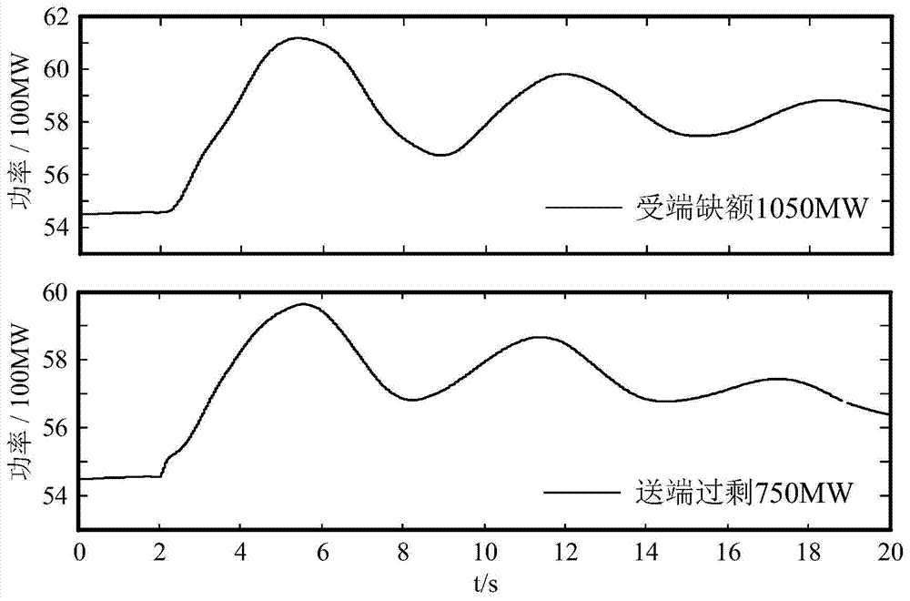
[0044] When the interconnection system is affected by the transient power disturbance impact in the area, it usually only takes a few seconds to cause a very high power swing peak on the tie line, such as figure 1 . The purpose of the present invention is to overcome the deficiencies of existing technologies such as DC large-mode power modulation, DC small-mode power modulation, bilateral frequ...


PUM


Abstract

The invention discloses an inhibition method for power fluctuation peak of a tieline. The inhibition method is characterized in that the start time and the end time of emergency DC control and the emergent power modulation rate are set to realize inhibition for the power fluctuation peak of the tieline. The method comprises the steps of measuring the power fluctuation data of the tieline in real time; starting the emergency DC control in the case that the power value of the tieline exceeds a start threshold, and determining the corresponding emergency DC power modulation rate according to the power fluctuation slope of the tieline, so as to perform emergency DC control; ending the emergency DC control once the power of the tieline reaches the fluctuation peak, that is, zeroing the emergency DC power modulation quantity. The invention also discloses an inhibition method for the power fluctuation peak of the UHV tieline. With adoption of the method, the problem of excessively high power fluctuation peak of the UHV tieline caused by the transient power shock disturbance can be inhibited, and the transmission capacity of the UHV tieline and the transient stability of an inter-regional interconnection system can be effectively improved.

Description

technical field [0001] The invention belongs to the technical field of electric power transmission and distribution, and in particular relates to a method for suppressing the power swing peak value of an UHV tie line. Background technique [0002] In the power system, the transmission voltage is generally divided into high voltage, extra high voltage and ultra high voltage. Internationally, high voltage (HV) usually refers to a voltage of 35 to 220kV; extra high voltage (EHV) usually refers to a voltage of 330kV and above and below 1000kV; ultra high voltage (UHV) usually refers to a voltage of 1000kV and above. For the vast majority of power grids in my country, low voltage refers to the voltage of 1kV and below; medium voltage refers to the voltage of 35kV; high voltage refers to the voltage of 66kV, 110kV and 220kV; ultra-high voltage refers to the voltage of 330kV, 500kV and 750kV The voltage; UHV refers to the 1000kV AC voltage technology that is currently being vigorou...

Claims


Application Information

Patent Timeline
Patent Type & Authority Patents(China)
IPC IPC(8): H02J3/24
CPCH02J3/24
Inventor 周鑫孙海顺文劲宇
Owner HUAZHONG UNIV OF SCI & TECH
Why Eureka
Try Eureka