Elongated stand pipe power response measurement device through simulating seabed pipe soil and horizontal forced oscillation

A technology of forced oscillation and dynamic response, applied in the field of marine engineering, can solve problems such as inability to adjust the shape of the riser, difficult vortex-induced vibration testing, and difficulty in underwater monitoring equipment, etc., to achieve the effect of easy upgrade and modification, and easy installation.

Active Publication Date: 2015-04-08
SHANGHAI JIAO TONG UNIV
View PDF8 Cites 6 Cited by
  • Summary
  • Abstract
  • Description
  • Claims
  • Application Information

AI Technical Summary

Problems solved by technology

Analyzing this test technology, it is found that its shortcomings are: 1. Considering the depth of the towing pool, it is generally only possible to simulate the vortex-induced vibration of small-scale pipe fittings, and it is difficult to effectively test the vortex-induced vibration at the real Reynolds number; 2. The interaction between the riser and the seabed is simulated through experiments; 3. It is not easy to arrange underwater monitoring equipment around the riser, and the shape of the riser cannot be adjusted during the slow-wave riser model test; 4. It is impossible to carry out a certain flow rate 5. The process of installing the riser in the experiment is more complicated; 6. It cannot effectively simulate the movement of the offshore platform

Method used


Image

  • Elongated stand pipe power response measurement device through simulating seabed pipe soil and horizontal forced oscillation
  • Elongated stand pipe power response measurement device through simulating seabed pipe soil and horizontal forced oscillation
  • Elongated stand pipe power response measurement device through simulating seabed pipe soil and horizontal forced oscillation

Examples


Embodiment Construction

[0032] The present invention will be described in detail below in conjunction with specific embodiments. The following examples will help those skilled in the art to further understand the present invention, but do not limit the present invention in any form. It should be noted that those skilled in the art can make several modifications and improvements without departing from the concept of the present invention, and these all belong to the protection scope of the present invention.

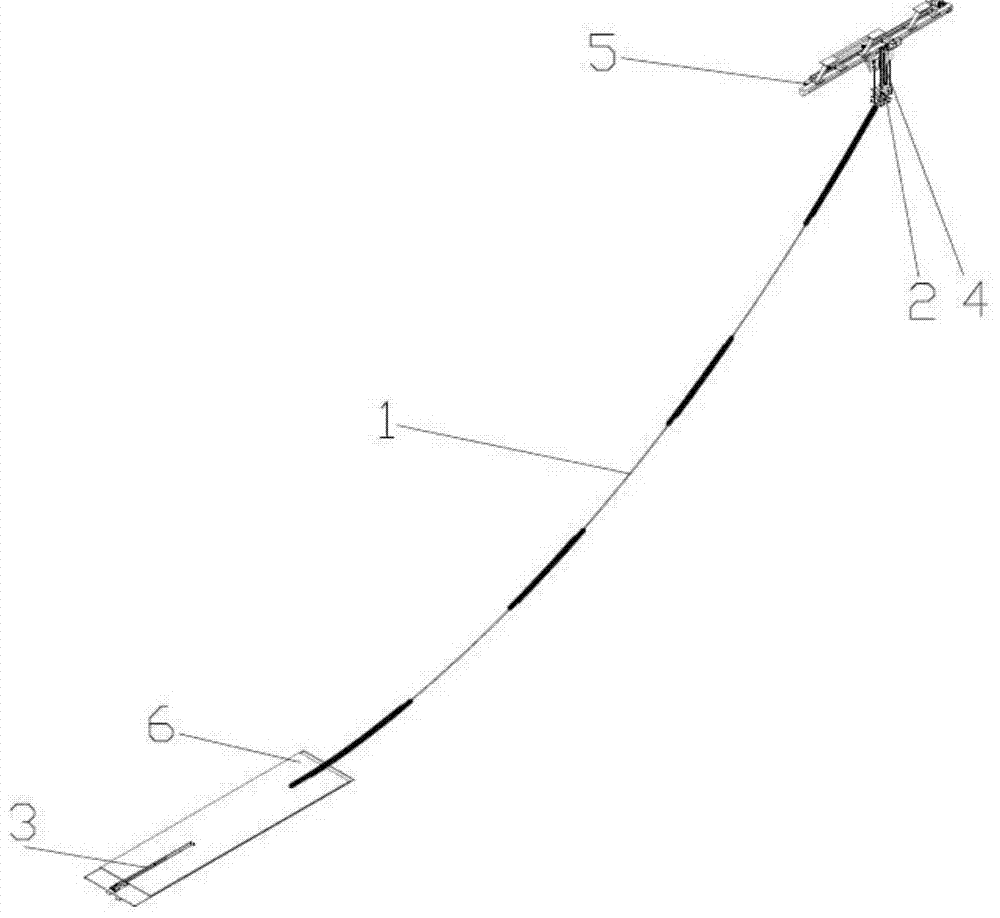
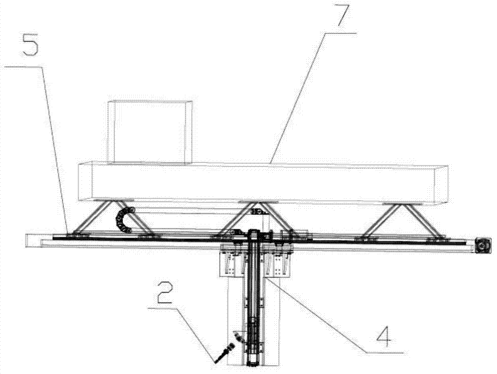
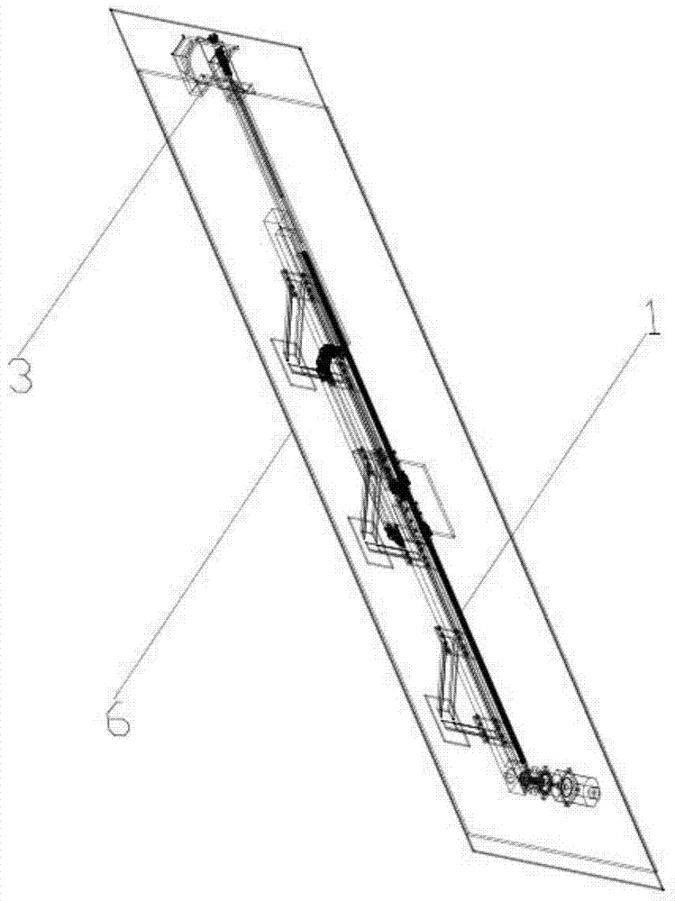
[0033] Such as figure 1 , figure 2 and image 3As shown, the device provided by the present invention includes: a deep sea riser module 1, a top boundary module 2, a bottom boundary module 3, a fixed module 4, a top sliding module 5, a bottom sand board module 6, and a measurement analysis control module 7, wherein: deep sea In the riser module 1, the top of the riser is connected with the top boundary module 2, and the bottom of the riser is connected with the bottom boundary module 3, wher...


PUM


Abstract

Provided is an elongated stand pipe power response measurement device through simulating seabed pipe soil and horizontal forced oscillation. The device comprises a deep sea stand pipe module, a top part boundary module, a bottom part boundary module, a fixing module, a top part slide module, a bottom part sand plate module and a measurement, analysis and control module. The two ends of the deep sea stand pipe module are respectively connected with the top part boundary module and the bottom part boundary module. The fixing module is connected with the top part boundary module and the top part slide module. The top part slide module is connected with the fixed end of the bottom part of a trailer. The bottom part sand plate module is connected with the bottom part boundary module and a pool small false bottom. The measurement, analysis and control module is respectively connected with the deep sea stand pipe module, the top part boundary module, the bottom part boundary module, the fixing module, the top part slide module and the bottom part sand plate module. Vortex-inducted vibration of the stand pipe with the movable top end can be tested by the device through simulating the seabed pipe soil effect and the horizontal forced oscillation state.

Description

technical field [0001] The invention relates to the field of marine engineering, in particular to an experimental device capable of simulating the action of seabed pipes and soil and measuring the dynamic response of a slender riser under horizontal forced oscillation, while monitoring vortex-induced vibration (VIV). Background technique [0002] Under the action of wind, wave and current, the marine floating structure will drive the catenary riser to make periodic reciprocating motions in the water, thereby generating a relative oscillating flow in the direction of riser movement, and this oscillating flow will encourage the standpipe to hang "Intermittent" vortex-induced vibration occurs in the section. Under the action of floating body motion and environmental load, the interaction between the riser and the seabed will cause very large bending stress on the riser, which is prone to fatigue damage. In recent years, with the development of deep-sea petroleum systems, caten...

Claims


Application Information

Patent Timeline
IPC IPC(8): G01M7/02G01N29/04
Inventor 苏琳陈逸凡曾亚东马磊鑫欧绍武蔡曦冯辉付世晓
Owner SHANGHAI JIAO TONG UNIV
Why Eureka
Try Eureka