
A fully sealed electromagnetic shielding impedance box

An electromagnetic shielding and fully sealed technology, applied in shielding devices and other directions, can solve problems such as not suitable for long-term signal acquisition, unfavorable power system promotion and use, poor sealing, etc., to achieve strong anti-electromagnetic interference ability, convenient and reliable wiring, and sealing strong effect

Active Publication Date: 2017-05-31
STATE GRID HENAN ELECTRIC POWER ELECTRIC POWER SCI RES INST +1
View PDF6 Cites 0 Cited by
  • Summary
  • Abstract
  • Description
  • Claims
  • Application Information

AI Technical Summary

Problems solved by technology

[0003] In addition, according to the actual needs of on-site measurement, sometimes it is necessary to take voltage signals from the end screens of multiple transformer bushings, the end of capacitive voltage transformers, multiple lines or the first ends of multiple dry-type shunt reactors, which cannot be used in many cases. A complete set of voltage divider measuring devices is used for measurement. Therefore, many scientific and technological testing institutions mostly use self-designed and custom-made suitable impedance boxes to form a measurement circuit with the test product. signal measurement
Generally, the custom-made impedance box adopts a single-layer design, and the sealing performance is poor. It is greatly affected by the surrounding electromagnetic field environmental factors and weather factors. It is not suitable for long-term signal acquisition. It is not easy to place due to the influence of wiring and geographical environment during measurement. The reliability is poor, which is not conducive to the promotion and use in the power system

Method used


Image

  • A fully sealed electromagnetic shielding impedance box
  • A fully sealed electromagnetic shielding impedance box
  • A fully sealed electromagnetic shielding impedance box

Examples


Embodiment Construction

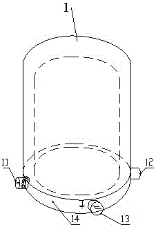
[0028] Such as figure 1 As shown, the present invention includes a box body 1 and a base 4, and adopts a modular design and a double-layer sealing arrangement. The outer side of the base 4 is conveniently provided with a grounding terminal 13, a coaxial cable jack 11 on the outer side of the base, and a coaxial cable jack 12 on the outer signal side of the base along the circumference.

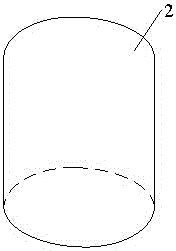
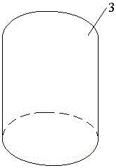
[0029] Such as figure 2 , 3 , 4, the box body 1 includes an electric field shield 2 and a magnetic field shield 3 that are sheathed together at intervals. There is a certain distance between them. The shapes of the electric field shield 2 and the magnetic field shield 3 are similar to the "bell" shape.

[0030] The electric field shield 2 is pressed into a U-shape using stainless steel material, and is fixed by three first spring buckles 9 used to fix the electric field shield 2 at the outermost edge of the base 4 during use, and can be directly covered by the magnetic field shield 3 The...


PUM


Abstract

The invention relates to a novel full-sealed electromagnetic shielding impedance box. The novel full-sealed electromagnetic shielding impedance box comprises a box body and a foundation, wherein the outer side of the foundation is respectively provided with a grounding end, a foundation outer side measurement end coaxial cable jack and a foundation outer side signal end coaxial cable jack in a circumference direction, the box body comprises an electric field shielding cover and a magnetic field shielding cover which are sleeved with an interval, the electric field shielding cover is arranged at the outer side of the magnetic field shielding cover, intervals are arranged between the top portion and circumference of the magnetic field shielding cover and the electric field shielding cover, and bottom portions of the electric field shielding cover and the magnetic field shielding cover are respectively provided with an opening. The method is more applicable to AC high voltage signal measurement in complex on-site test environments and can realize long-time measurement without influence of external factors such as, an electromagnetic environment, rain, snow, dust storm, on-site wiring and disposing position.

Description

technical field [0001] The invention relates to the field of test devices for measuring AC high-voltage signals, in particular to a test device for measuring AC high-voltage signals for substation system debugging. Background technique [0002] At present, the high-voltage signal measurement generally adopts a complete set of resistive voltage divider, capacitive voltage divider or resistive-capacitive voltage divider device manufactured by the manufacturer. Practical experience shows that resistive voltage dividers have high requirements for the quality of resistive components. Even if a surface discharge occurs on the resistive film of the components, the overall resistance or failure of the resistive voltage divider will result in poor long-term stability and high manufacturing costs. And the higher the voltage level is, the worse the response characteristics are, and it is rarely used now; for the capacitive voltage divider, it basically does not consume the AC active po...

Claims


Application Information

Patent Timeline
Patent Type & Authority Patents(China)
IPC IPC(8): G01R1/18
Inventor 郭磊张晓鹏张科董曼玲丁国君王天王伟王立楠王震宇李晓纲李予全郑含博
Owner STATE GRID HENAN ELECTRIC POWER ELECTRIC POWER SCI RES INST
Learn More